I've always wanted a proper digital microscope for inspecting solder joints and PCB traces, but commercial options are either too expensive for what you get, or too cheap to actually be useful. And, where's the fun in buying one pre-made? So, I built my own using a Raspberry Pi Zero 2W, the 12.3 megapixel HQ Camera, and a custom SPI SD card interface to surpass my original digital microscope project in every way.
Materials
Required
- Raspberry Pi Zero 2W
- Raspberry Pi HQ Camera (IMX477)
- Pi Zero CSI ribbon cable adapter (22-pin to 15-pin)
- 8GB+ SD card for the OS
- HDMI monitor (1080p) + mini-HDMI adapter
- USB-C power supply (5V, 1A recommended)
- C-mount microscope lens
- Mounting hardware-- M2x8mm and M3x8mm screws
I also strongly recommend a LED ring light with a polarizing filter, since this microscope needs a LOT of light at full zoom.
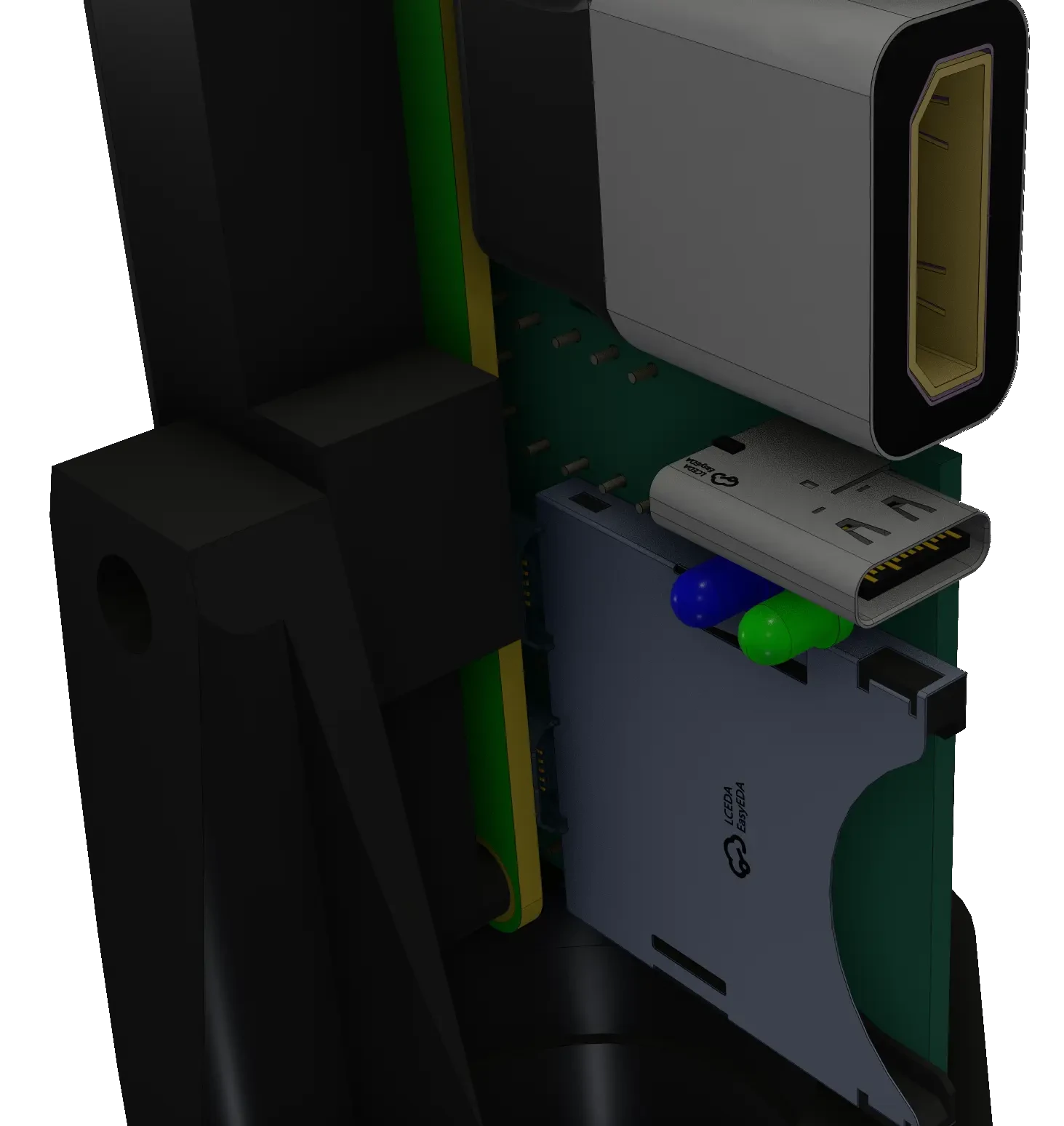
Electronics
The custom PCB used consists of a:
- Full-size SPI SD card slot
- Through-hole USB-C port
- 2x momentary pushbuttons
- 1x red LED
- 1x blue LED
- 1x green LED
- 470µF 10V aluminum polymer bulk capacitor
- Various passives-- full schematics with values are on Github
Tools
- Soldering iron
- Multimeter for testing
- Screwdriver
As always, all source code, configuration files, and PCB design files are available on this project's Github Page.
The Build
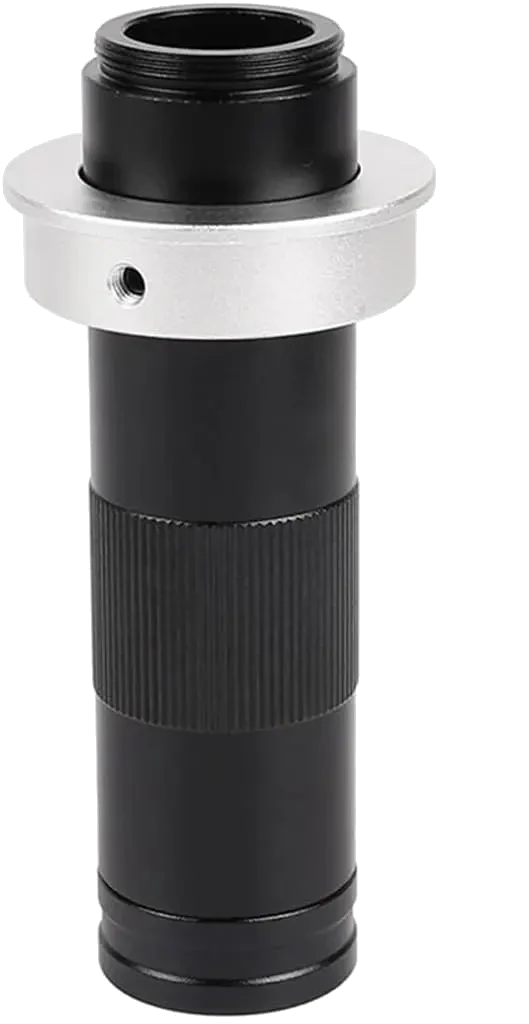
The C-mount lens I used
This project was built to replace the outdated digital microscope I made nearly 3 years ago. it worked great for the time, but since then I've improved my skills significantly, and enough problems plagued it that I decided it was time for a rebuild.
To make it a worthwhile improvement, I wanted more features, like:
- Image saving capability
- Real, variable zoom
- An actual power-on/off button
The previous design had none of these, so it wasn't much more than a fun toy I could use to examine things around my workshop. Factoring in that the mount it used was 3d printed and flimsy, and it made it very difficult to get a stable, in-focus image, especially with the fixed focal length macro lens I was previously using.
Since I wanted to use an actual microscope lens, I searched around for the best camera architecture for this project, and landed on a Raspberry Pi HQ camera module, with a C-mount microscope lens. Paired with a Raspberry Pi Zero 2W, I had enough compute to read the entire 12.3MP camera sensor at a reasonable framerate.
Component Explanation
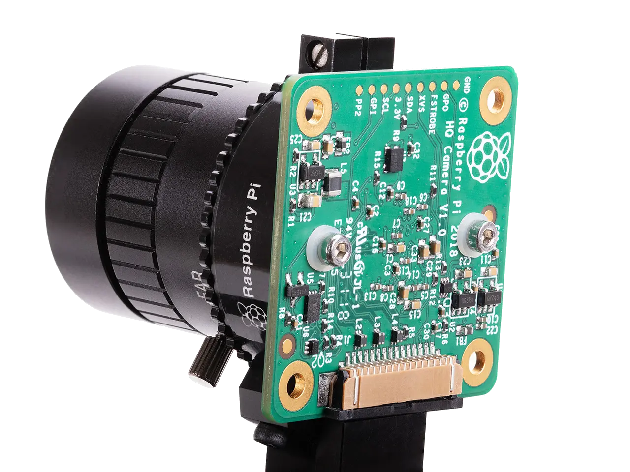
Raspberry Pi HQ Camera module
The Raspberry Pi HQ Camera uses a Sony IMX477 sensor (Type 1/2.3") with a 12.3 megapixel resolution (4056×3040) and a proper C/CS lens mount. Compared to the standard Pi camera modules, the difference in image quality is night and day. There's less low-light noise, a sharper image, and it overall feels like a more premium product.
The Pi Zero 2W serves as the brain of the system. It runs Raspberry Pi OS Lite (Trixie) headless, with no desktop environment, and the live camera preview is rendered directly to the HDMI output using the GPU's DRM/KMS pipeline. This means that the CPU is only at about 25% utilization during normal operation, leaving plenty of headroom for future compute, and keeping the enclosed Raspberry Pi from generating too much heat.
For storage, I wanted the photos to be easily removable without needing to SSH in or pull the main SD card. So I wired up a secondary SD card slot over the Pi's SPI0 bus. The system writes photos to this removable card by default, and falls back to the internal SD card if the SPI card isn't present.
The SPI SD Card Interface
SPI SD card slot
One of the more interesting parts of this build was getting a secondary SD card working over SPI. The Pi Zero 2W only has one native SDIO interface, and that's used by the boot SD card. However, the Linux kernel has an mmc_spi driver that can drive an SD card over any SPI bus, albeit at a lower speed than native SDIO.
I wrote a custom device tree overlay to register the SD card slot on SPI0, using GPIO8 as chip select, GPIO9/10 for data, and GPIO11 for the clock. After compiling the overlay and adding it to the boot configuration, the secondary card shows up as /dev/mmcblk2, a block device that can be formatted and mounted like any other drive. It's formatted as FAT32 for maximum compatibility, so I can pull the card and read it on any computer since I had some trouble with ext4 writing on the Raspberry Pi.
Power & Illumination
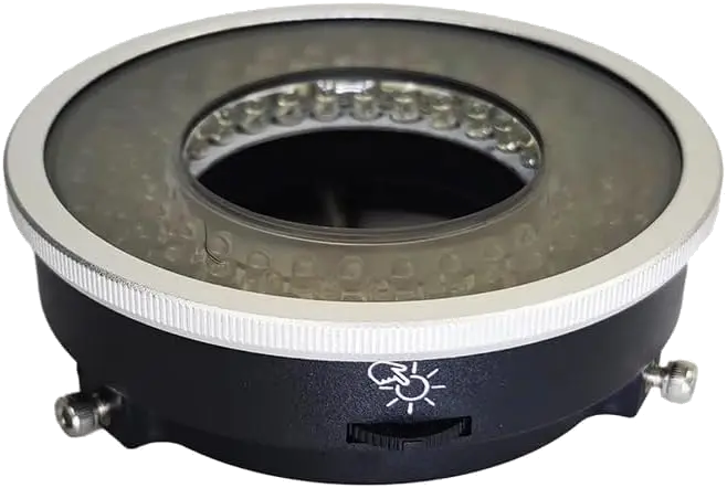
Polarizing filter + ring light
The LED ring light and polarizing filter are powered from the same 5V USB-C supply as the Pi, sharing the power rails. The LED array, mounted to the bottom of the camera lens, as close as possibleto the specimen draws about 0.5A when fully on, and since it's switched on all at once, I added a 470µF aluminum polymer capacitor at the power split point to handle the inrush current. Although I just happened to have some high-quality aluminum polymer capacitors on hand, the low ESR of aluminum polymer is actually important here, since all the LEDs switch on at once, meaning that the inrush current could potentially cause instability in the Raspberry Pi during operation. That lower ESR means that the voltage sag from the power supply won't be as extreme, keeping the system from brownouts and unintended reboots. This also allows the microscope to operate under lower power USB-C power supplies, so it's more versatile.
GPIO Layout
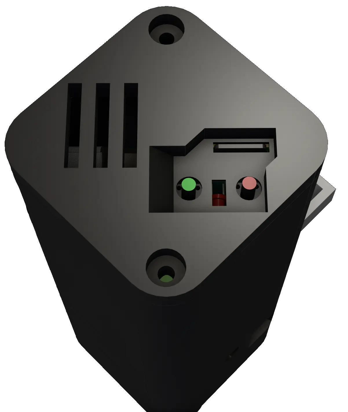
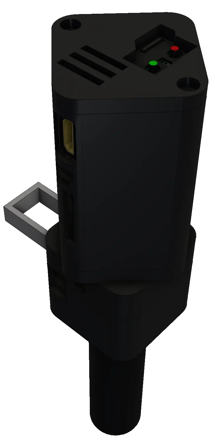
Power, Photo buttons and LEDs
The physical interface is intentionally minimal since size was something I wanted to optimize for. Two buttons and three LEDs:
- GPIO2: Photo button. Takes a full-resolution 12.3MP still when pressed.
- GPIO3: Power button. Cleanly halts the Pi on press, and wakes it back up on the next press, without touching the power supply.
- GPIO5: Blue LED. Lights up while a photo is being written to the SD card.
- GPIO6: Red LED. Solid during capture, blinks twice to confirm the photo was saved.
- 5V-in: Green LED. Always-on power LED to indicate that the device is ready to be activated.
GPIO2 and GPIO3 are the I2C1 pins on the Pi, which meant I had to disable the I2C1 peripheral in the boot configuration to free them up for button use. Thankfully, the HQ Camera communicates over a separate I2C bus through the CSI connector, so disabling I2C1 doesn't affect the camera at all.
The Software
The software is a single Python file that handles the camera preview, photo capture, LED feedback, and SD card management. It's designed to start automatically on boot via a systemd service and run indefinitely with no user interaction beyond button presses.
System Architecture
main()
 ├── LEDController          GPIO5 (blue) + GPIO6 (red) via gpiozero
 ├── StorageManager         SPI SD (preferred) → internal SD (fallback)
 ├── CameraManager
 │    ├── picamera2          1080p30 DRM preview (GPU-rendered)
 │    └── rpicam-still       Full-res 4056×3040 JPEG capture
 └── InputManager           GPIO2 photo button via gpiozero
The live preview runs at 1920×1080 at 30fps using picamera2's DRM/KMS backend. This is rendered entirely by the VideoCore GPU, which means that the preview frames never touch the CPU. This worked so much better than previous attempts, which aimed to load each frame and display them through python, which crippled the display's resolution and framerate to just a few fps. With this method, I removed a huge amount of overhead, and I can't notice any dropped frames on the final output, even at 1080p.
The Full-Resolution Capture Problem
This was the most interesting engineering challenge of the project. The Pi Zero 2W only has 512MB of RAM, with 256MB allocated to the Contiguous Memory Allocator (CMA) for DMA buffers. My first approach was to use picamera2's built-in switch_mode_and_capture_file function, which temporarily reconfigures the sensor from the 1080p preview mode to the full 4056×3040 resolution, captures one frame, and switches back.
However, there was a problem: memory. Each full-resolution frame in BGR888 format is roughly 37MB, and picamera2 allocates multiple buffers during the mode switch for its internal pipeline. Worse, those buffers weren't being released properly: CMA free memory would drop by ~37MB per capture, then only recover at about 2MB/s. Even though an initial photo would be saved just fine, after one or two more, the system would run out of CMA and crash.
My solution was to sidestep picamera2 entirely for the capture step. Instead, the code fully closes the picamera2 instance (releasing the camera device), shells out to rpicam-still as a subprocess, and then reopens picamera2 to restart the preview. rpicam-still manages its own buffer lifecycle and cleans up completely when it exits, so there are no memory leaks. The unfortunate tradeoff is that the preview goes black for about 2-3 seconds during the capture. I'm sure someone out there knows how to fix the memory leak, but the display blackout is short enough that I don't really mind it. It even has an upside; when the microscope is very zoomed in, even touching it briefly makes the entire image wobble. Having a 1-2 second delay before the image is taken ensures that the sensor is no longer being shifted by my finger pressing the photo button.
The JPEG produced by rpicam-still is initially written to /tmp, which is a tmpfs (RAM-backed filesystem), so the initial write is instant and doesn't wear the internal SD card. It's then moved to the SPI SD card with an explicit fsync on both the file and the parent directory, ensuring the FAT32 metadata is flushed before the blue LED turns off. I haven't measured write speeds directly, but since only a single photo can be taken every few seconds, I doubt that write speeds will become the bottleneck.
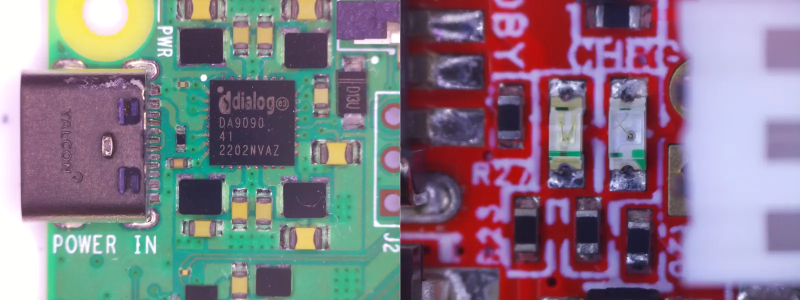
In the end, though not the absolute ideal solution, this method provides absolutely beautiful close-up shots of whatever circuit I'm examining, and I was blown away by the zoom capabilities of this lens. More sample photos can be found in the gallery on my Github.
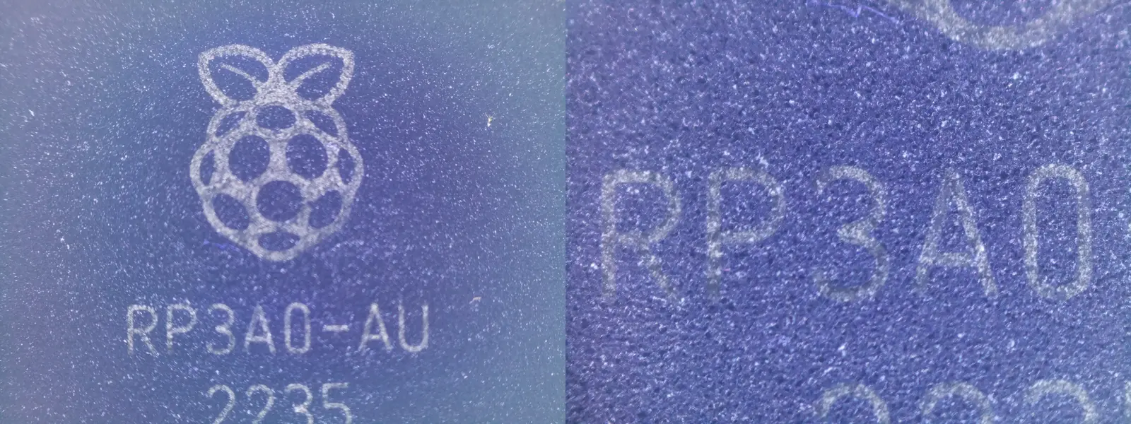
The Raspberry Pi Zero 2W's RP3A0-AU SoC at maximum zoom
Boot & Service Configuration
The system starts automatically on boot via a systemd service. The service does a few important things: it kills the tty1 login getty (so no text bleeds through when the DRM preview drops during capture), and zeroes the framebuffer to ensure a clean black screen. The power button on GPIO3 is handled entirely by a device tree overlay; when pressed, the kernel initiates a clean shutdown, and the bootloader monitors GPIO3 during halt to trigger a wake-up on the next press.
3D Printing & Enclosure Design
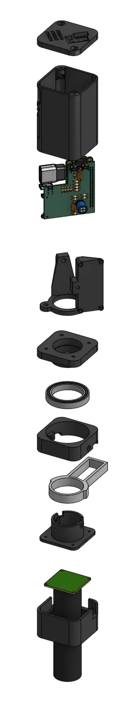
Exploded view of the whole microscope assembly
Once the hardware and software were designed and tested, I moved on to the 3D-printed enclosure. I made the case as small as possible while still fitting the Raspberry Pi HQ Cameras module and the Raspberry Pi Zero 2W + HDMI adapter. The final footprint for the microscope was 53mm x 53mm, and 143.5mm tall (not including the camera lens). I figured the tradeoff between height and length/width was worth it, and it makes it look sleeker in my opinion.
The entire microscope assembly was designed to mount to a desk-mounted microscope boom stand. The arm has a maximum extension of 20 inches, and has 5 separate height/angle adjustment points, as well as a final fine-pitch height adjustment knob before the microscope is attached. This means that in addition to tuning the focus of my microscope, I can also adjust how far I want to zoom in. I can get just centimeters above the specimen for up-close die shots, and get a foot or more away for soldering work, with barely any compromise on zoom ability.
I designed the enclosure in multiple stages, each one stacked and screwed on top of the last. In total I had seven stages, which is a lot of extra assembly for a project. This for two main reasons:
- The mechanism for mounting the microscope to the microscope mount was more involved than expected.
In order to mount the microscope to the microscope mount, the lower half of the assembly had to be slotted into the desktop mount, then screwed into place using two thumbscrews. Only after that could additional parts of the assembly be mounted.
Additionally, since the entire build required that parts be assembled sequentially, and I specifically wanted to avoid any 3D printing any parts with overhangs that would require supports, the number of parts increased substantially.
- I wanted to experiment with a system that would alleviate cable strain.
Secondly, a few more stages were added because I wanted to implement a feature that would relieve one of the most annoying aspects of my old digital microscope design: cable strain. With previous designs, because of the thickness of most HDMI cables, and the relative lightness of the 3D printed mounts for my microscopes, the HDMI cable would pull the entire microscope along until the cable strain was relieved. This meant that some angles were impossible to capture, and that every time I adjusted the height of the camera, the entire scope would shift.
To fix this, I placed the entire Raspberry Pi assembly on a large 6807 bearing. I picked this bearing because its OD of 47mm meant it would be able to fit within the 53mm2 enclosure, and its 35mm ID meant that the ribbon cable connecting the HQ camera module to the Raspberry Pi Zero 2W would be able to comfortably fit through, and flex as the upper half of the microscope rotated. This means that the strain from the HDMI cable will be relieved as the entire upper half of the microscope could rotate to correct for the incoming angle of the HDMI cord. Additionally, this means that the monitor can be placed essentially anywhere relative to the microscope, since the bearing and internal cables allow for at least 360° of rotational freedom.
In addition to adding explicit strain relief to all cables entering the microscope, I also internally powered the ring light that illumintates the specimen I'm observing. The ring light I bought came with a polarizing filter, which is incredibly useful for reading part and serial numbers off of ICs, but it also came with a USB-A connector on the end of a very long cable. So, after measuring out about 40cm from the ring light, I snipped the rest of the wire off, stripped the positive and negative terminals from the cord, and soldered them directly to the same 5V rail that was powering the Raspberry Pi, alongside the 470uF aluminum polymer capacitor.
The 3D-printed enclosure was designed with a small hole to let the cable enter the assembly, then travel through the center of the bearing before reaching the upper electronics, so that the upper assembly could still rotate freely while the ring light stayed stationary.
Conclusion
The microscope works exactly as intended, and it's a huge improvement over previous designs. The live preview is smooth and responsive, the full-resolution captures are more than sharp enough to inspect individual solder joints, and the removable SD card makes it trivial to pull photos for documentation or sharing. The whole system boots in under 30 seconds and is fully functional and ready to use with no configuration.
Full microscope, with upper assembly rotated at a 45° angle
What I Would Improve
-
Eliminate the capture blackout: The 2-3 second preview drop during photo capture is the biggest usability compromise. A Pi with more RAM (like a CM4 with 2GB+) would allow
picamera2to handle the mode switch internally without CMA exhaustion, keeping the preview live during capture. -
Higher SPI SD card speed: The
mmc_spidriver is limited to SPI clock speeds, which means write performance is significantly slower than native SDIO. For single JPEG captures this is fine, but if I ever wanted to add video recording to the SPI card, I'd need to look into SDIO-based solutions or a USB card reader. -
Mount Wobble: Since I used a mount that clamps to a desk, it wasn't the most sturdy. It was definitely a huge improvement over the 3D-printed mount from revision #1, but the camera stream still wobbles any time I touch the microscope itself. An even more sturdy mounting system, and perhaps electronically-actuated positioning would be cool improvements, but the stream wobble isn't enough of a problem for me to go out and fix it.
-
Custom PCB Errata: The current prototype is on a custom PCB, but there are a few problems with the design. Namely, I added a 10kΩ series resistor on the GPIO3 line, which meant that the firmware couldn't sufficiently recognize when it was pressed. I just fixed this by shorting the resistor with a wire. Secondly, there isn't a dedicated spot to solder on the 470uF capacitor or the ring light wires. I solved this problem by just soldering them to the PCB where the Raspberry Pi's pin header peeked out, then adding hot glue for strain relief, but a proper place for them to be soldered would have been ideal, since there was definitely space. Additionally, since this was one of my first PCBs designed after I switched from EasyEDA to KiCAD, the schematic and layout are functional, but a little messy.
Final Thoughts
This project was a fun intersection of embedded Linux, camera systems, and bare-metal GPIO work. I'm considering adding video support in the future if I find I could use it (I've always wanted to record my own reflow soldering process,) but for now this satisfies all my needs. If you're interested in building your own, all of the source code, device tree overlays, and configuration files are available on GitHub. Additionally, I put together a small photo gallery showing off more photos taken by this microscope. Thanks for reading!