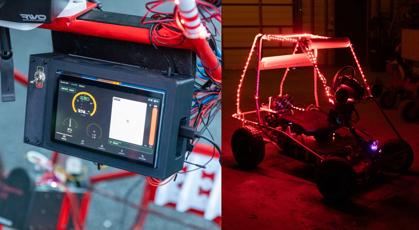
Starting in my senior year of high school, I was in talks with the head of house for the SMCS magnet program to create a more impressive robotics project than any other previous class. After leading my robotics class for an entire semester, we ended up with a fully functioning remote-controlled electric gokart, with the works. This is how we made the SMCSKart's dashboard, the brains of the operation.
Since this blog post will be the first of many in my series about this electric gokart (which I will refer to as the SMCSKart for the rest of the blog post), and the gokart is by far the most complex project I've been a part of, the materials list will only encompass the components I purchased through admin, and is available as a spreadsheet. Insignificant tools and smaller parts will be omitted from the list to keep it concise.
As always, the full design files can be found on GitHub, as well as the complete documentation for the entire SMCSKart here.
Introduction
Just a few weeks into my senior year at Poolesville High School, Ben Ross, Sam Ross, and I were chatting with the SMCS head of house, Kevin Lee, and we ended up on the topic of our second-semester robotics class. This robotics class was one of two options that the SMCS senior class could take, the other option being the Nand2Tetris curriculum. In years past, the robotics curriculum had mainly consisted of building Raspberry Pi-powered robots, and extending the class to include edge-computed AprilTag and facial recognition to follow a person around the classroom. Since the class was available exclusively to SMCS seniors, the level of rigor was essentially what you made of it; after all, not everyone was interested in robotics or computer architecture, so the easier 8th-period class the final semester before college was a bit of a treat for everyone.
This year, however, knowing the caliber of students that we had in our graduating class, Mr. Lee wanted to push us to build something truly special. Our sister magnet program at Montgomery Blair High School had created a segway from scratch for their robotics class, and we simply couldn't take that sitting down. After brainstorming ideas, Mr. Lee jokingly suggested a gokart. It stuck. And here we are.
The Design
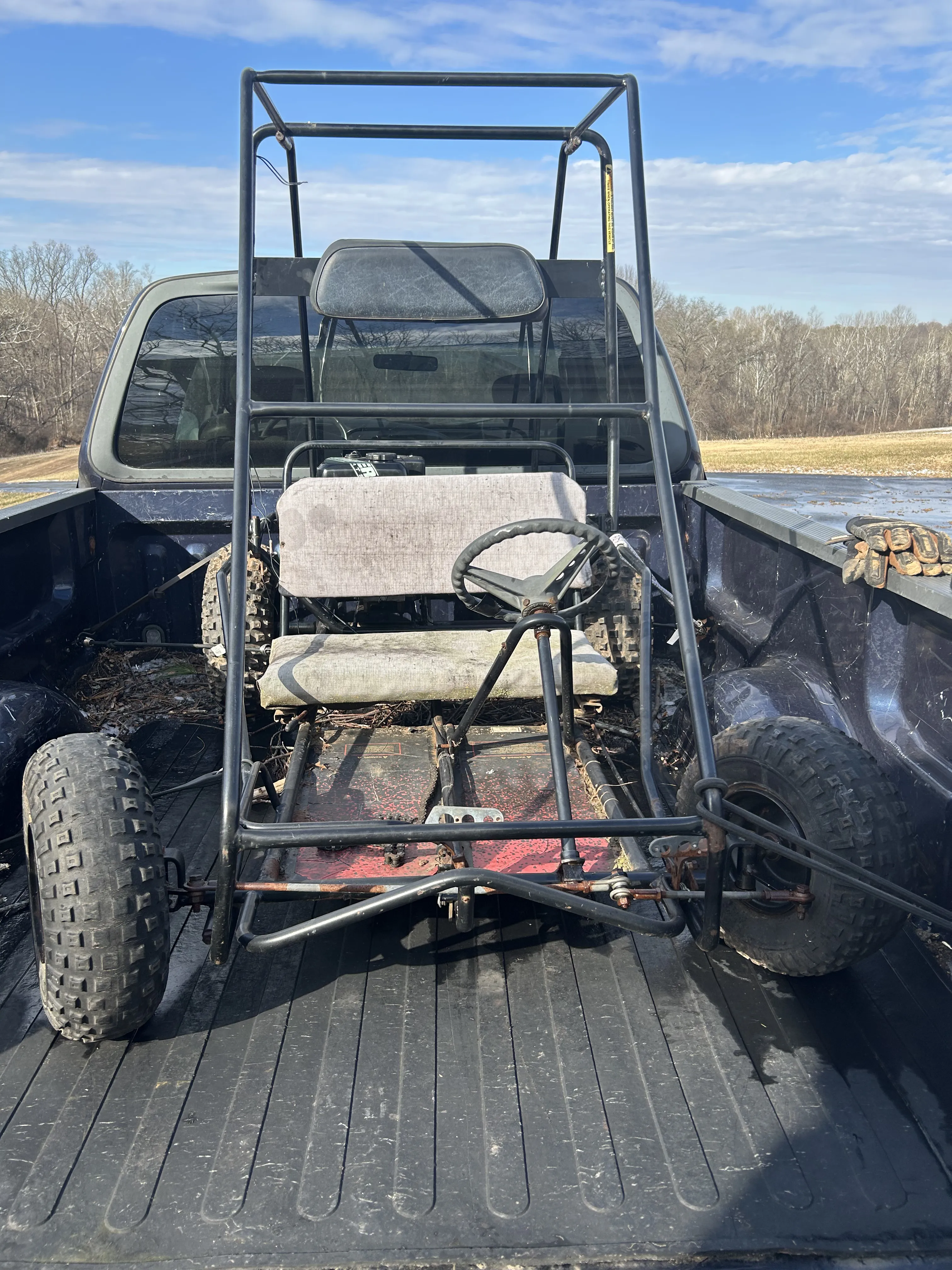
Photo of the gokart frame fresh from Facebook Marketplace
The basic premise we decided on was to create an electric gokart that could be remotely operated. Beyond that, the design was totally left up to the class. All we were given was an old, rusted gas-powered gokart frame that I picked up on Facebook Marketplace a few days earlier.
On the first day of class, I led a brainstorming session the entire class period. By the end, we had a clearer plan for what we wanted to accomplish. We wanted a fully remote-controlled gokart that could steer itself, drive itself, have infrastructure for autonomous driving, as well as LED lights, and a paint job to match. All of this needed to be controlled centrally, with an architecture that could support all of the features that our class wanted to include, all the features that future classes might want to implement, all while being accessible and simple enough for future years to iterate on our design.
Compute Architecture
Our dashboard architecture utilizes two separate processors: a Raspberry Pi 4 and a Teensy 4.1. The Raspberry Pi 4 was selected for its appeal in edge-compute and low-power applications, and would be what drove our UI, displayed on a 7" touch LCD screen. The Raspberry Pi's job was to handle all of the non-critical aspects of the SMCSKart's electrical system: the display UI, the GPS mapping using OpenStreetMap, any camera vision work we might do, etc. The Teensy 4.1 was chosen because of its high performance, while still being a deterministic microprocessor; running at 600 MHz, it would blaze through any low-level control workload we could throw at it, all while responding within milliseconds to user inputs. The Teensy's job was to handle interfacing with all other peripherals: the steering motor, the motor speed controller, the LEDs, the radio transceiver, and all the sensors that we used.
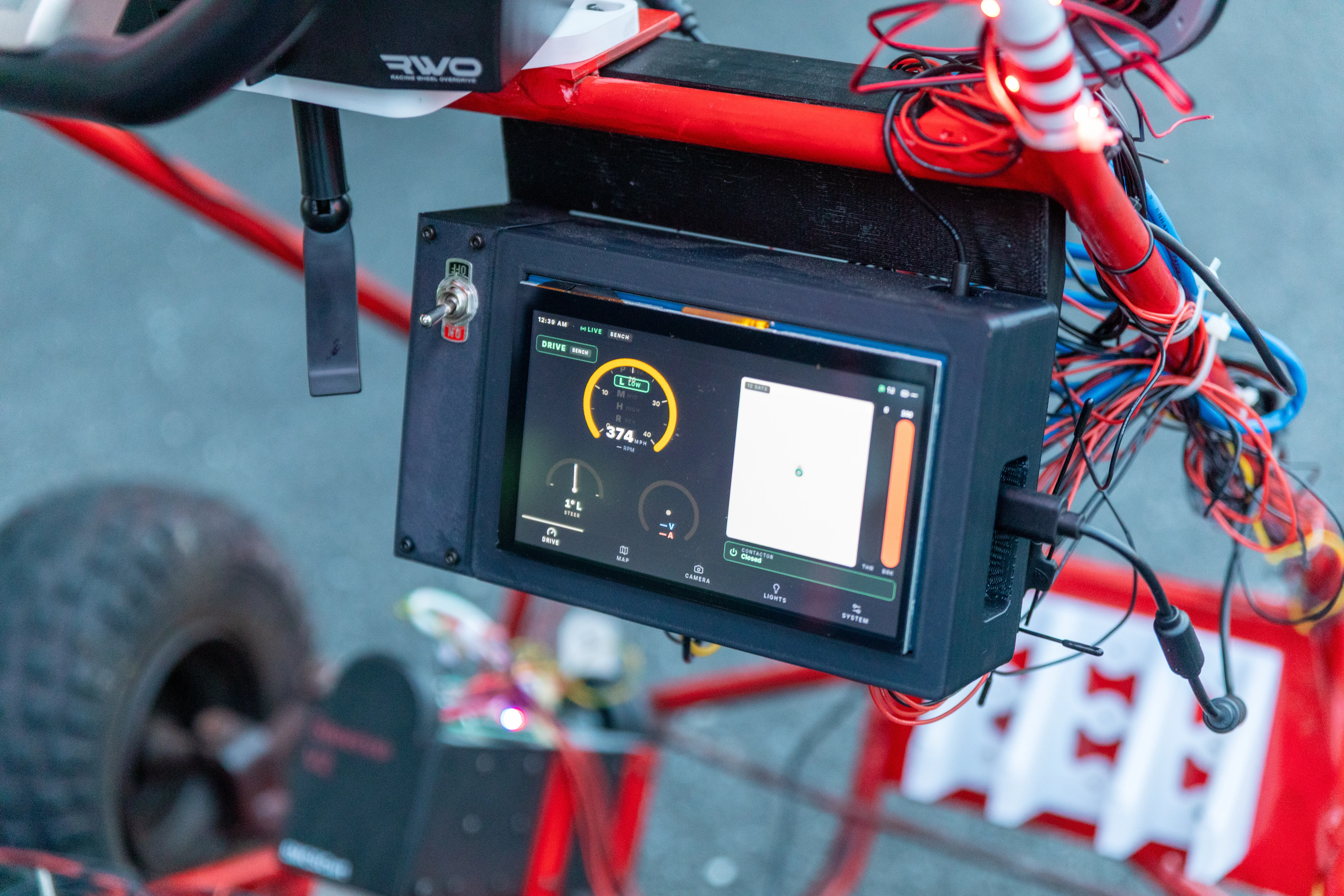
Photo of the dashboard mounted to the SMCSKart, displaying its UI on a 7-inch touchscreen
The dual computer/microcontroller architecture split that we used was essential for this project. In most other applications, a single Raspberry Pi would have been fine. However, any computer running a modern operating system has the potential for lockups and stuttering. Even with automatic updates and WiFi turned off, and a stable distro picked on a known stable batch of Raspberry Pi 4s, the nature of the OS's task scheduler means that certain safety-critical events could get deferred for something as simple as a background process wanting to index a filesystem. Those safety-critical signals arriving at the GPIO late could be the difference between safely stopping and crashing. Driving any vehicle is a constant closed control loop between the pilot and the vehicle. Any perceptible delay, let alone full feedback dropout, is extremely jarring to the user, and even a second of lost control can be unrecoverable in many circumstances. For that reason, using only a Raspberry Pi was untenable for our gokart's compute architecture. Using a microcontroller to handle every input and output meant that unless it was physically turned off, the microcontroller was far less likely to stall. Simply forgoing an operating system allows much more control over the commands executed, and by extension, much more reliable I/O.
I/O Requirements
The main job of the Teensy 4.1 is to facilitate communication between the selected human input devices and the controllers that drive the kart. Although the electronic speed controller (ESC) and steering motor (Steervo) interfacing will be discussed in more depth in the other blog posts on this topic, they both have fairly distinct criteria:
ESC:
- The throttle pin (27) is analog, from 0.5v - 4.3v. Must be powered from the ESC's dedicated throttle power pin (28)
- Braking, reversing, and gearshifting I/O are digital and active-low
- Speedometer telemetry is a digital input
- The RS232 programming port uses TTL levels despite its name
Steervo:
- The CAN_H/CAN_L bidirectional pair needs a 120Ω termination
- The position feedback loop is local to the Steervo
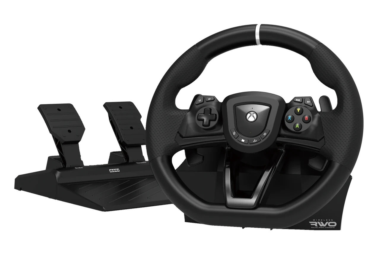
Stock photo of the racing wheel we used to control the SMCSKart
Radio Transceiver
- Low-latency hardware UART connection
- 5V power
- I/O connector placed with the transceiver's antenna in mind
Hori Xbox Steering Wheel
- Easy access to the USB-A port
- Strict quality control on the USB design; signal dropouts on control hardware are not an option
Criteria & Constraints
The most important constraint that drove all of the development for this PCB was repairability. It would have been easier, not to mention smaller and sturdier, to simply utilize SMD components for all of my discrete logic. In that case, the largest sections of the board would be taken up by sockets and connectors, not the ICs themselves. However, I know that no matter how well I design or protect this mainboard, it will eventually break or fail. In that event, the repair process needs to be as easy as possible for that generation of SMCS students. This is why I opted for a 100% through-hole component design. That way, any student in the class could theoretically replace every component on the board, not just the select few with SMD soldering experience.
Component Paradigm
This meant budgeting a lot more room for through-hole components. What could've been done in just a few square centimeters using 0402 resistors, capacitors, and SOT form factor transistors instead had to be laid out using 1/4-watt axial resistors and TO-220 package MOSFETs. Using those larger components did come with the added benefit of a wider design margin when it came to current handling and maximum operating limits, but the added mass of those components will also likely serve to weaken solder joints and internal wirebonds over time significantly faster than a smaller, lighter package soldered tighter to the PCB.
For the more expensive components, I made extensive use of sockets to maximize repairability. The Teensy 4.1, GPS module, CANBUS transceiver, and throttle DAC are all socketed. Beyond repairability making the board look like a PCB from the late '80s, the other important criteria were that all the connectors were easily accessible, and that the board itself fit into the footprint of the largest part of the dashboard; in this case, the 7" LCD.
Connector Paradigm
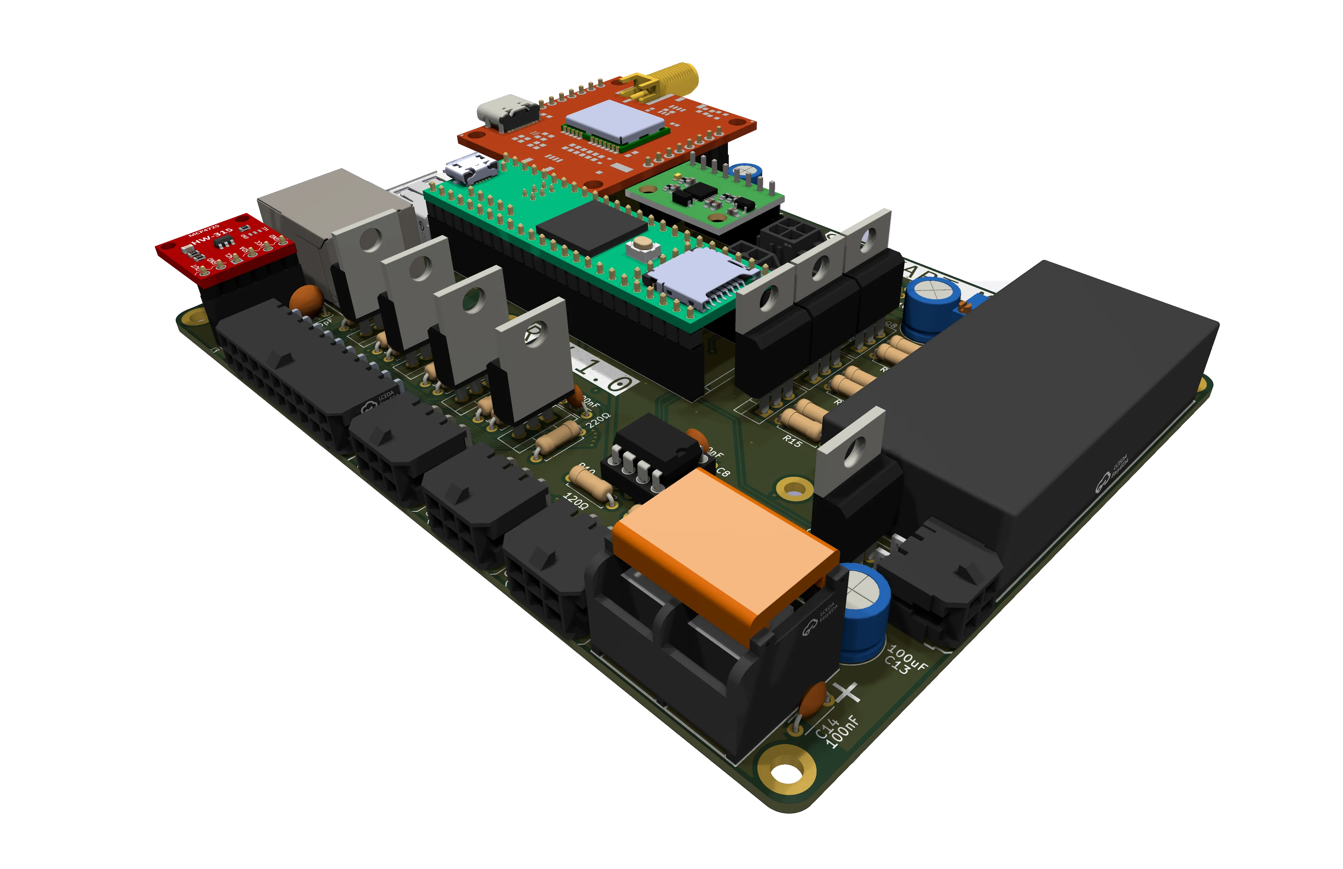
3D rendering of the mainboard, showing the MX3.0 connectors on the bottom edge of the mainboard
With a hard limit on the size of the PCB, not every connector could fit on the edge. All motor/drivetrain-facing connectors pointed out the bottom of the dashboard, imitating a diagnostic port underneath a modern car. This placement gave them priority orientation to travel to the ESC the quickest, since that distance was the longest and noisiest for any signal to travel. The contactor and Steervo connectors followed close behind, with the contactor connector facing out of the left side of the dashboard. On the right side of the dashboard, a USB-A host port and a 100 Mbps Ethernet connector wire directly into the Teensy 4.1. In the middle of the board, four smaller 4-pin vertical connectors provide adequate I/O for the LED lighting, as well as the radio transceiver.
All of the connectors (with the exception of the USB and Ethernet on the Teensy 4.1) utilize Molex MX3.0 locking connectors. This was my first experience using Molex connectors in this way, but given the heightened vibrational stress that every connection in the SMCSKart would be under, it made sense to opt for locking connectors that approach automotive-grade security. Since they're reminiscent of motherboard connectors, I was a lot more confident that vibration wouldn't knock them loose, compared to typical Dupont, or even JST connections.
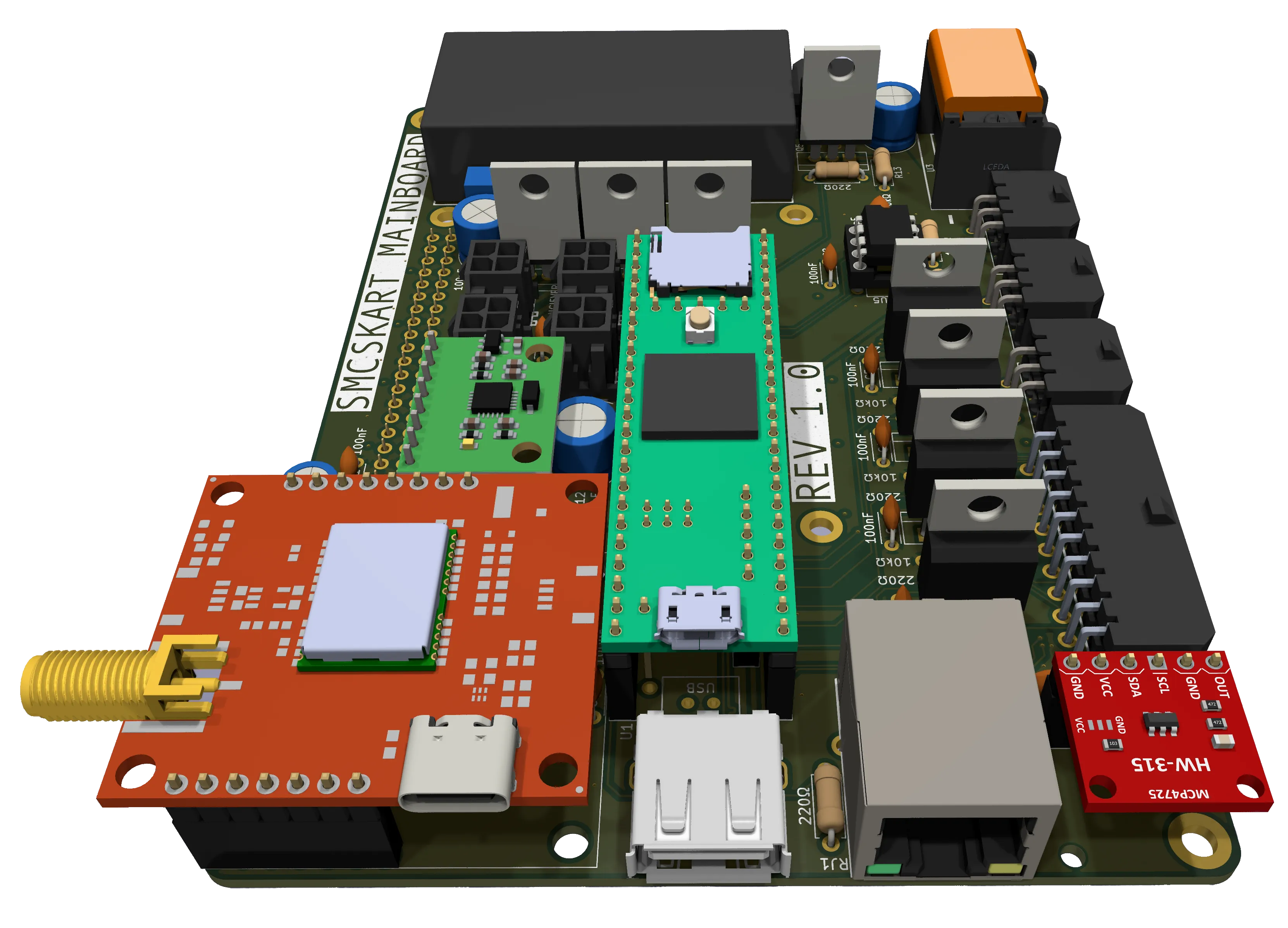
3D rendering of the mainboard, showing the USB-A and Ethernet ports next to the Teensy 4.1
The Teensy 4.1's USB and Ethernet play an important role as well. Although the Teensy 4.1 cannot be programmed through its second USB port, it can operate both as a host and a peripheral. In our configuration, the extra USB port was dedicated to our steering wheel, a Hori Xbox Racing Wheel. Although our architecture will never come close to saturating that USB peripheral's bandwidth, the USB D+/D- traces were carefully length-matched and impedance-controlled to 90Ω on the 4-layer FR4 board.
The Ethernet port was originally intended for advanced networking throughout the SMCSKart. I had plans for everything to communicate on a local, peer-to-peer wired network to make software design as easy as possible, but as the project progressed it turned out that adding network overhead didn't matter nearly as much as I had anticipated; the main communication requirement, between the Teensy 4.1 and Raspberry Pi 4, was handled using a short, length-matched UART connection on the PCB itself, which would be more reliable than any external networking. Regardless, just like the USB-A port, this Ethernet port's data wires were also carefully length-matched and impedance-controlled to 100Ω.
The final connector on the mainboard is the GPS antenna. A dedicated hole on the top of the dashboard enclosure makes room for the SMA connector to accept an antenna tuned for GPS frequencies.
Risk Mitigation Paradigm
One of the most critical parts of designing something like the SMCSKart is that the system is responsive at all times. This means that in addition to utilizing a mix of operating systems, super-loops, and redundant/error-resistant communication protocols, the control logic needs to correct for loss of control, and mitigate it. We made extensive use of watchdog timers to check whether the Teensy 4.1 was still responding, and to reboot it if necessary.
That handles software errors, but hardware errors, such as a loss of power or a brownout, are a different problem, and need to be solved in a different way. All major components are decoupled with a mix of ceramic capacitors and aluminum polymer capacitors to blend high capacitance with low ESR. This helps to buffer inrush current and smooth out transients and noise, reducing the risk of a brownout event in the Teensy 4.1 or Raspberry Pi 4. However, none of that matters if a power delivery error occurs upstream of the mainboard. In this case, all outputs are configured by the Teensy 4.1 to be pulled low, which is supplemented by pull-down resistors on the mainboard itself. In the event of a dead microcontroller, the SMCSKart just rolls to a stop. Even in the worst-case scenario of an error so extreme that the microcontroller is actively trying to accelerate, cutting power to the control system completely immobilizes the data bus communicating with the Steervo and ESC, preventing a runaway event on the hardware level.
Power Architecture
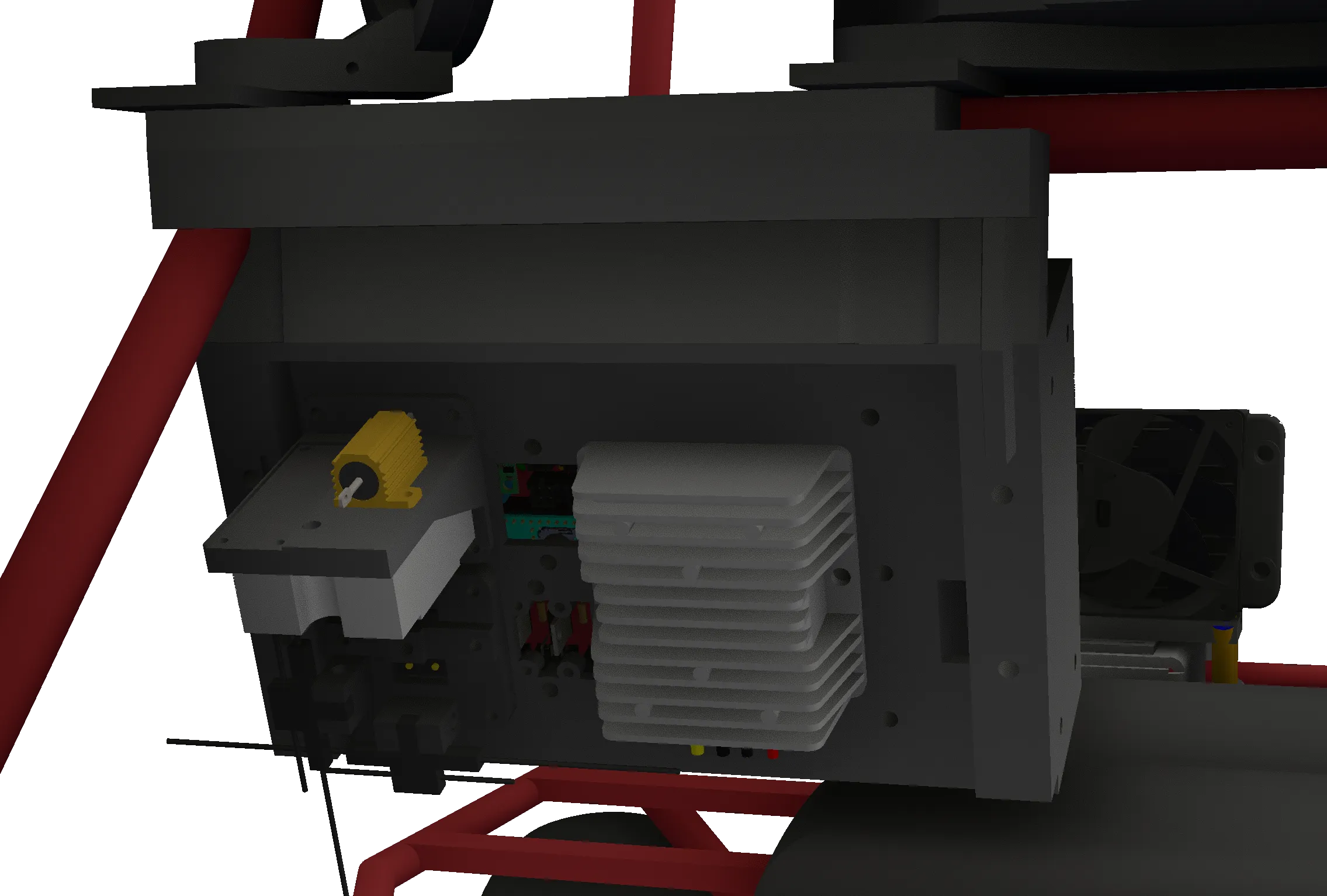
3D rendering of the rear of the dashboard, showing the 24v buck converter next to the precharging module
There are a lot of competing voltage levels in this design, like in any electric vehicle. In total, there's ~77v, 24v, 5v, and 3v3. The entire kart is powered from the battery pack, which in its 24s1p configuration achieves a nominal pack voltage of 76.8v. From there, VBATT is converted to 24v using a standalone, waterproof 20A buck converter connected to the back of the dashboard assembly. The mainboard is supplied 24v, which is the highest raw voltage used by it, exclusively to run the precharge contactor and LED strips. From 24v, a soldered buck converter module drops the voltage from 24v to 5v, which is used to power the Raspberry Pi 4, LCD, and Teensy 4.1. The 3v3 logic level is generated primarily by the PMIC on the Raspberry Pi 4 and Teensy 4.1, and is used exclusively for logic level communication.
Signal Integrity
On an EV, the sheer size of the inductive load that the motor creates means that everything else sharing a common ground is subject to some level of interference and noise. However, using best design practices can keep interference to a minimum.
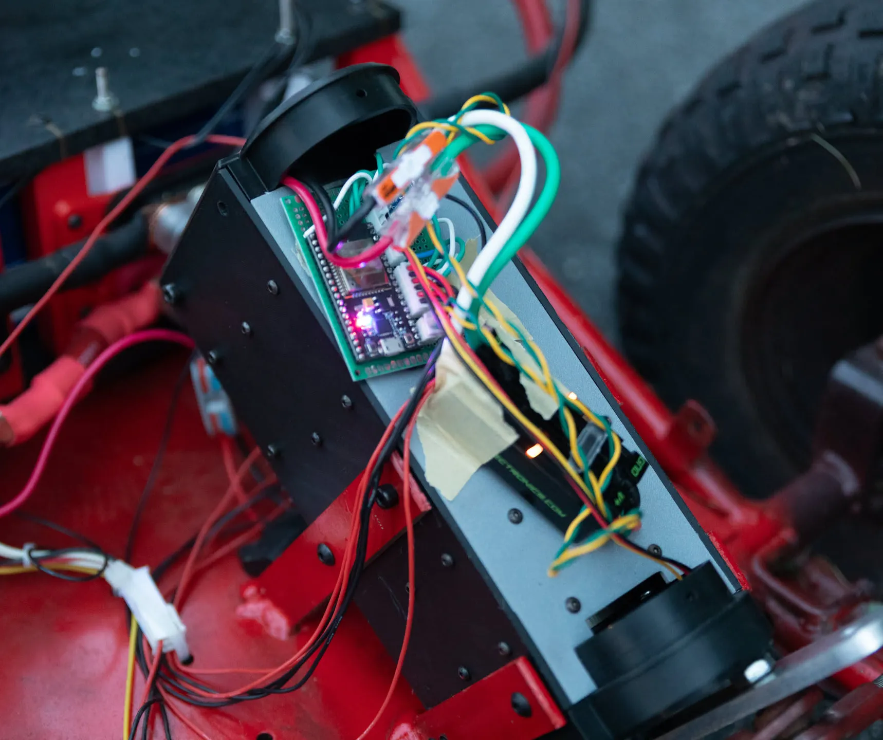
Zoomed-in photo of the Steervo control board. Details in a future blog post
So, with that in mind, I paid especially close attention to grounding practices, and I spent extra time tuning high-speed data traces to be as closely impedance and trace matched as possible. Although the mainboard has clearly indicated outputs for USB, Ethernet, and CANBUS, only USB was used to the extent described in our original scope. Ethernet has been explained, but CANBUS ended up not being fully used because of a datasheet misinterpretation for the motor controller we purchased for the Steervo. We used the Talon SRX, and although it advertises CANBUS functionality, that functionality is gatekept by their own closed ecosystem. Essentially, we couldn't use the robust automotive-grade CAN protocol that we wanted to without shelling out another $100 for their branded central controller. Instead, we pivoted and utilized a multi-processor approach; we used a 250kbps CAN link to communicate with a CANBUS transceiver on a smaller Steervo control board. That took care of the largest potential source of error: the long, unshielded wires that ran from the mainboard all the way down to the Steervo. Paired with an ESP32, that CANBUS transceiver would translate CAN data into a PWM signal that the motor controller could interpret, albeit with a loss of the controller's internal PID loop. More on that in a future blog post.
Beyond using noise-resistant data protocols, I utilized two ground planes on the two uppermost copper layers. The top layer created a solid ground plane for EMC shielding and heat dissipation from high-power components, like the buck converter. The second layer, right underneath the prepreg, serves as a closer ground reference for the impedance-controlled data lines.
Thankfully, nothing on the board failed due to noise injection or flyback voltage spikes. I think this was in part due to the length of the current-carrying cables; their length likely added enough inductance to smooth out the most damaging transients.
Manufacturing
Actual assembly was easy enough; THT components are trivial to solder, and anyone in that class could have done it. The most nerve-wracking part of the process was that in a few cases, I had only purchased a single component. This meant that if the board was wrong, I'd not only need to wait on a respin from JLCPCB, but I'd also need to re-order select components, and pay an additional shipping fee.
Additionally, the control board wasn't fully ready for production until a couple of weeks into the semester, so it was a race against the clock to get it up and running; a respin would have taken until the end of the semester to even arrive, let alone characterize and test.
Testing
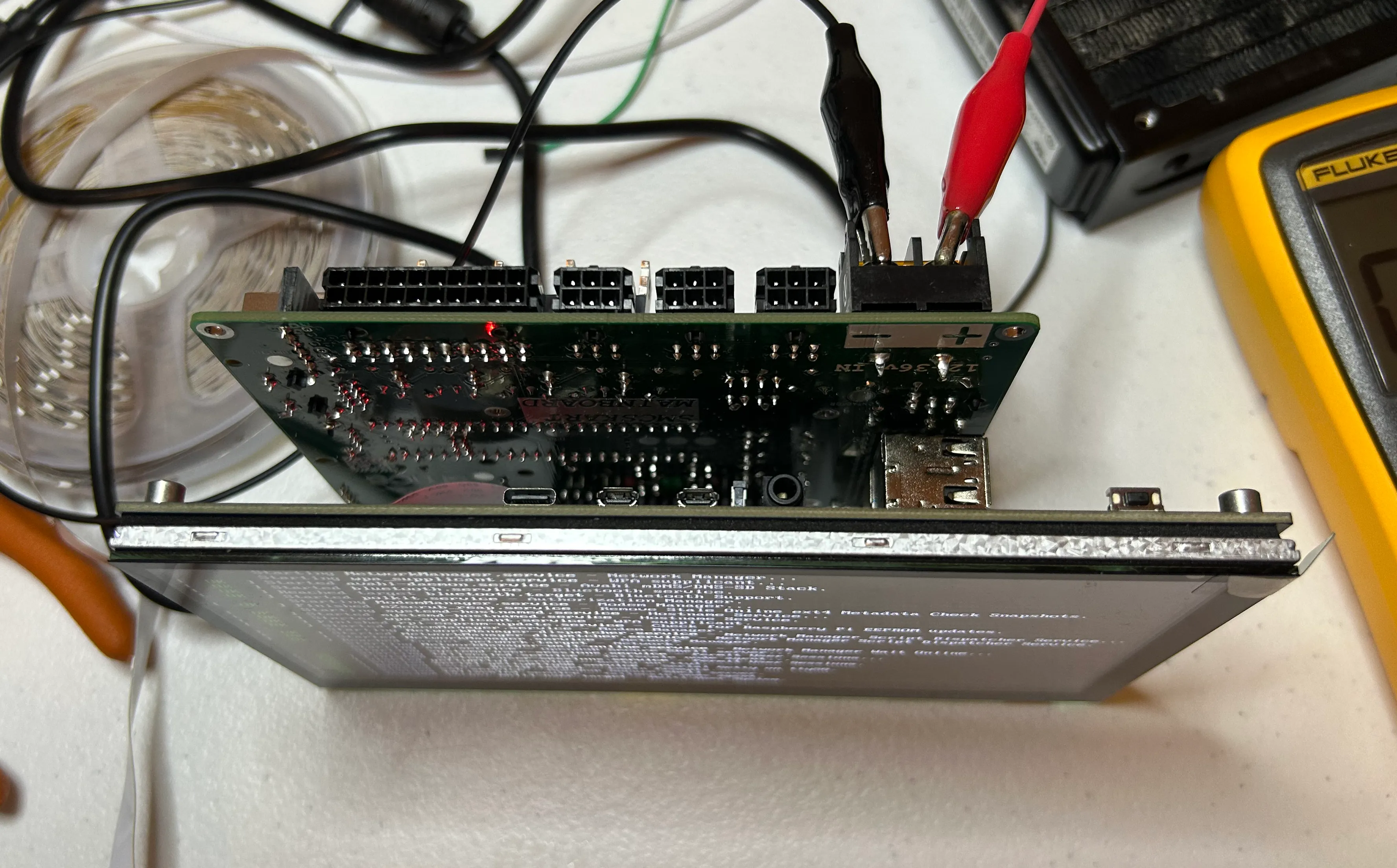
First dashboard bringup using the mainboard's power distribution
Testing occurred in phases, and progressed pretty fast to start. Once the coding team got their hands on the PCB, the LED strips got powered within a day, and the radio transceiver communication protocol (CRSF) was reverse engineered soon after. We set up a test where our radio controller directly changed the colors of the LED strips based on the throttle position, and we were able to get reliable real-time communication all the way across our school; the signal only started to drop out after there were six walls between the transmitter and receiver.
Next, the UART bridge between the Raspberry Pi 4 and Teensy 4.1 was tested. That got brought up quickly too, and soon the touchscreen dashboard was able to fully communicate with the microcontroller, through the Raspberry Pi 4.
After that, while the rest of the class was developing their parts of the project, the GPS module finally arrived. Testing that required the antenna to be out in the open air, so our testing rig (a bench power supply clipped to the 24v power terminals on the mainboard) was brought outside, tethered by an extension cable. Once we verified that our GPS module worked, it only took a few hours to get the dashboard UI written for real-time GPS positioning and tracking.
We spent a fair amount of time debugging a very esoteric error regarding the steering wheel. On some uploads, the steering wheel would be recognized and the Teensy 4.1 would interpret signals properly. Other times, it would go dark. Uploading the same exact code would produce different results; we were baffled by this seemingly nondeterministic steering wheel. Eventually, we found a convoluted workflow where a human would flash the code manually, as we isolated the cause of the missed enumerations to Claude's flashing process. About a month later, I identified that the real problem was a minor version mismatch on the Teensy USBHost_t36 library. The Arduino CLI's core worked, but the library packaged with PlatformIO was out of date. After patching the ID table, the problem was resolved.
After a while, the SMCSKart frame was ready, and the connectors could be checked. The reverse, high-speed, low-speed, and braking pins all worked flawlessly out of the box. However, I spent hours debugging the DAC that controlled the throttle. The throttle needed a signal between 0 and 4.3 volts that was supplied by the ESC. This meant having a noise-isolated 5v signal running into the mainboard, kept separate from the 5v used to power the Teensy 4.1 and Raspberry Pi 4. That wasn't the issue. The Teensy 4.1 wasn't able to send I2C commands to the DAC, which I solved by adding forgotten pull-up resistors on the SDA and SCL lines. After that, the DAC was even responding with proper voltage levels, yet the ESC wasn't seeing them. After hours of debugging, retracing my steps, looking at datasheets, and strongly considering that our ESC was broken, I noticed: I had forgotten to solder a single resistor on the DAC's output filter. The DAC's signals never left the mainboard.
After that embarrassing fix, the throttle registered properly, and we were able to get impressive results on our bench tests, with motor RPMs above 7000. Under no load, the motor drew only 1000 watts to sustain that speed. The last debugging step involved the CANBUS transceiver IC. I misread the datasheet, and inadvertently flipped the UART TX and RX lines. A simple wire bodge job fixed that, and CAN communication between the mainboard and Steervo controller worked well after that, at a reduced bitrate.
Conclusion
Although the mainboard took a few weeks to be fully characterized, with a few simple bodge jobs, the board fully worked. When we hooked it up to the battery pack, it turned on and worked. When we brought the SMCSKart off of the test rig for the first time, it worked. Pushing 7.2kW through the motor, the mainboard stayed operational the entire time, despite the voltage drop on the battery pack during kart acceleration.
I was blown away by the skills of my peers during the project. The speed that the coding team developed full-stack firmware still shocks me, and the other design and building teams were seriously involved in getting this project done as fast as possible. Future blog posts will focus more on them.
This was a great way for me to spend my final semester of 8th periods, and I'm so grateful to the unsung heroes of this project: the faculty. Without the support from Mr. Lee and the main office approving purchase orders, this project never would have left the drawing board. As a token of thanks, I inscribed the names of every engineer who worked on this project on the back of the mainboard. I hope that the next time the dashboard is taken apart for maintenance, the next class will be inspired by the work that we all put in.
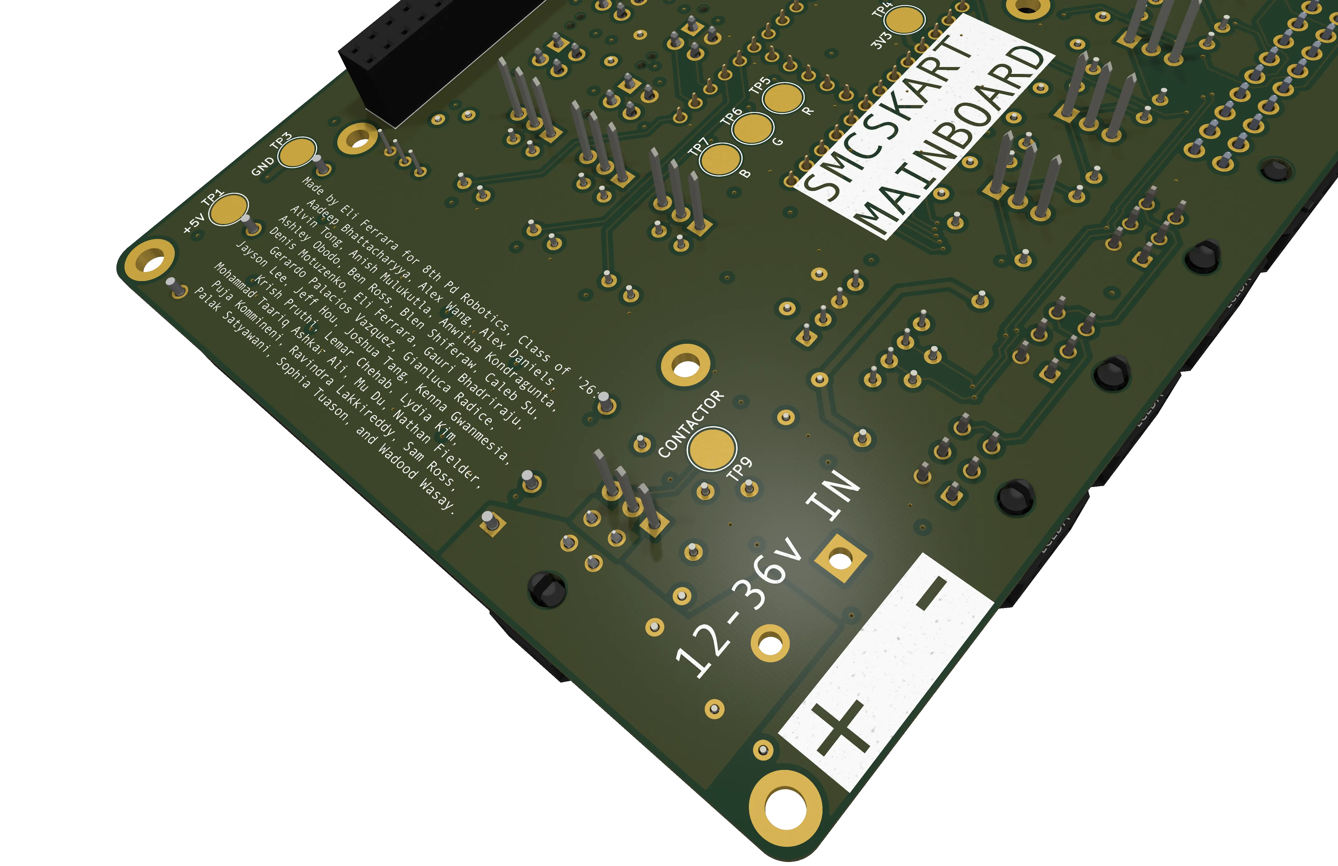
3D rendering of the bottom of the SMCSKart mainboard, showing the names of the 2026 SMCS Robotics class
Thanks for reading! I know this was a long one, but there's bound to be more! You can check out the documentation for the board itself here, and check out the software monorepo here. Additionally, the software documentation website has extremely thorough explanations of everything regarding the hardware-software stack. If you're looking for more information, before emailing me, check it out first. Blog posts #2 and #3 coming soon!