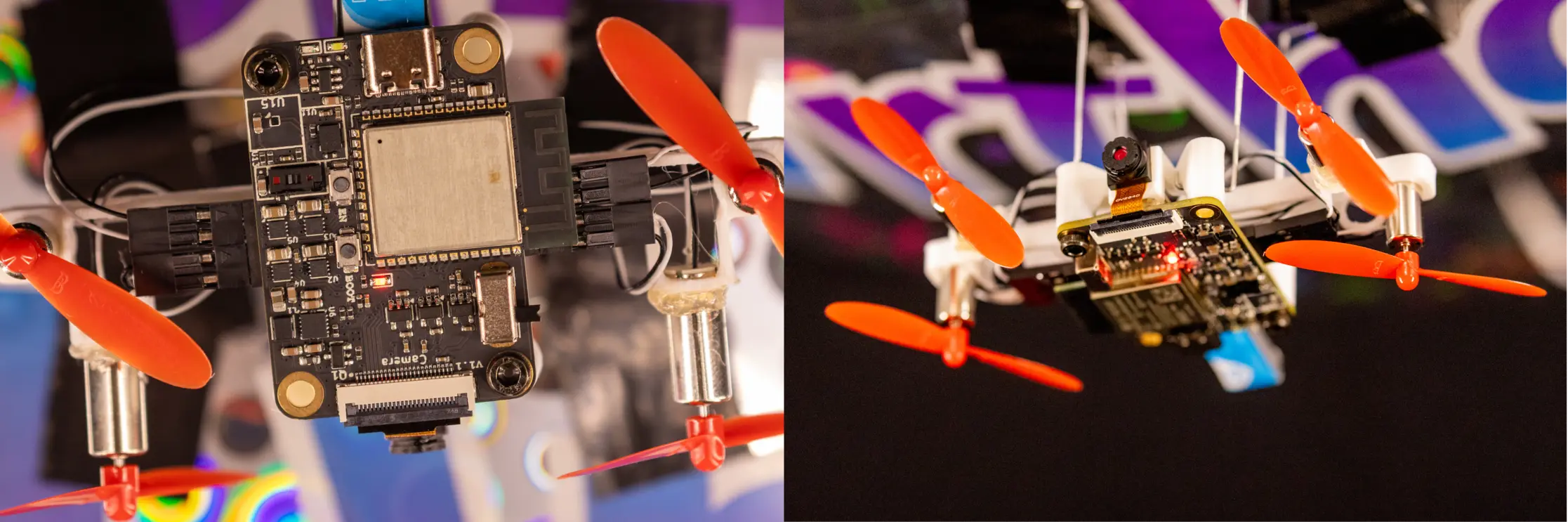
After spending six revisions perfecting a Raspberry Pi Zero 2W motor hat for the Falcon Flight project, I found myself staring at a board that worked flawlessly. It carried the 10th grade SMCS class at Poolesville High School into the most successful blimp project turnout ever, and I couldn't have been prouder. Then, I got an email.
PCBWay, a popular overseas PCB manufacturing company contacted me, curious if I was going to make any future revisions to the Falcon Flight design. Between the last time I worked on that board and the time I had received that email, over a year had passed, and I had learned a lot since then. I was more than happy to continue improving on the project, especially since I had some ideas in the back of my mind on how to improve it. This time, zero compromises.
Background
If you haven't read the Falcon Flight blog post, here's the short version: Falcon Flight was a custom PCB I designed as a motor driver hat for the Raspberry Pi Zero 2W, built for indoor autonomous blimps in the PHS SMCS program. Over six revisions, I learned an enormous amount about power distribution, motor driver design, sensor integration, and PCB layout. The final revision worked flawlessly, and dozens of boards are now in the hands of students.
But throughout that entire process, the Raspberry Pi was always the bottleneck. It consumed the majority of the power budget, mandated a 5V boost converter, and its GPIO header ate into the board's footprint. Worse, the Pi's boot time and general-purpose Linux overhead made it a poor fit for real-time motor control. After a certain point, there were no further optimizations I could have made without biting the bullet and switching to an entirely new architecture.
When PCBWay offered to sponsor a new board, I had the opportunity to do exactly that: design a standalone flight controller that combined the processor, camera, sensors, and motor drivers into a single, ultra-lightweight PCB. I named it Falcon Core.
Design Philosophy
Falcon Core wasn't intended to be a revision of the Falcon Flight project; instead, its purpose was to be an entirely new board designed to complete the same objective as the Falcon Flight board, lighter and smaller than ever before, with a different set of constraints. Where Falcon Flight was a hat constrained to the Pi's 65×30mm footprint and 40-pin header, the Falcon Core's dimensional constraint is far looser: is a self-contained system on a 32×46mm 4-layer PCB. Every component was carefully chosen specifically for this application, with the weight budget in mind.
The blimp uses a mylar balloon that provides approximately 80 grams of lift. That's not a lot. The electronics stack, including the board and the camera module, needed to come in well under that to leave room for the battery, 3D-printed gondola, motors, and wiring. My target was 11.5 to 13 grams for everything except the battery and motors, and every design decision was filtered through that constraint. One of the largest mass-reducing wins for this project was the use of a single battery. In years past, to get around the punishing voltage dip caused by inrush current to the motor drivers, two separate batteries were used; one for logic, one exclusively for motor power. In addition to the added weight of an extra battery, PCB space was taken up by additional switching and charging circuitry, and vertical room had to be allotted for the batteries to lay flat on the PCB itself. However, using a high-performance switching voltage regulator with documented voltage dip specs circumvented this issue, letting this board use only a single battery, becoming lighter than ever before.
The other major shift was the processing model. Falcon Flight ran everything on the Pi: motor control, sensor fusion, camera streaming, and (eventually) computer vision. With Falcon Core, I split responsibilities. The ESP32 handles real-time motor control, sensor polling, attitude and direction estimation, and streams camera data over Wi-Fi to a laptop, where OpenCV could handle the computationally expensive work like optical flow and AprilTag detection. Results come back over WebSocket, which keeps the firmware lean and the control loop fast, while offloading the work that's intractable for a microcontroller.
The Microcontroller
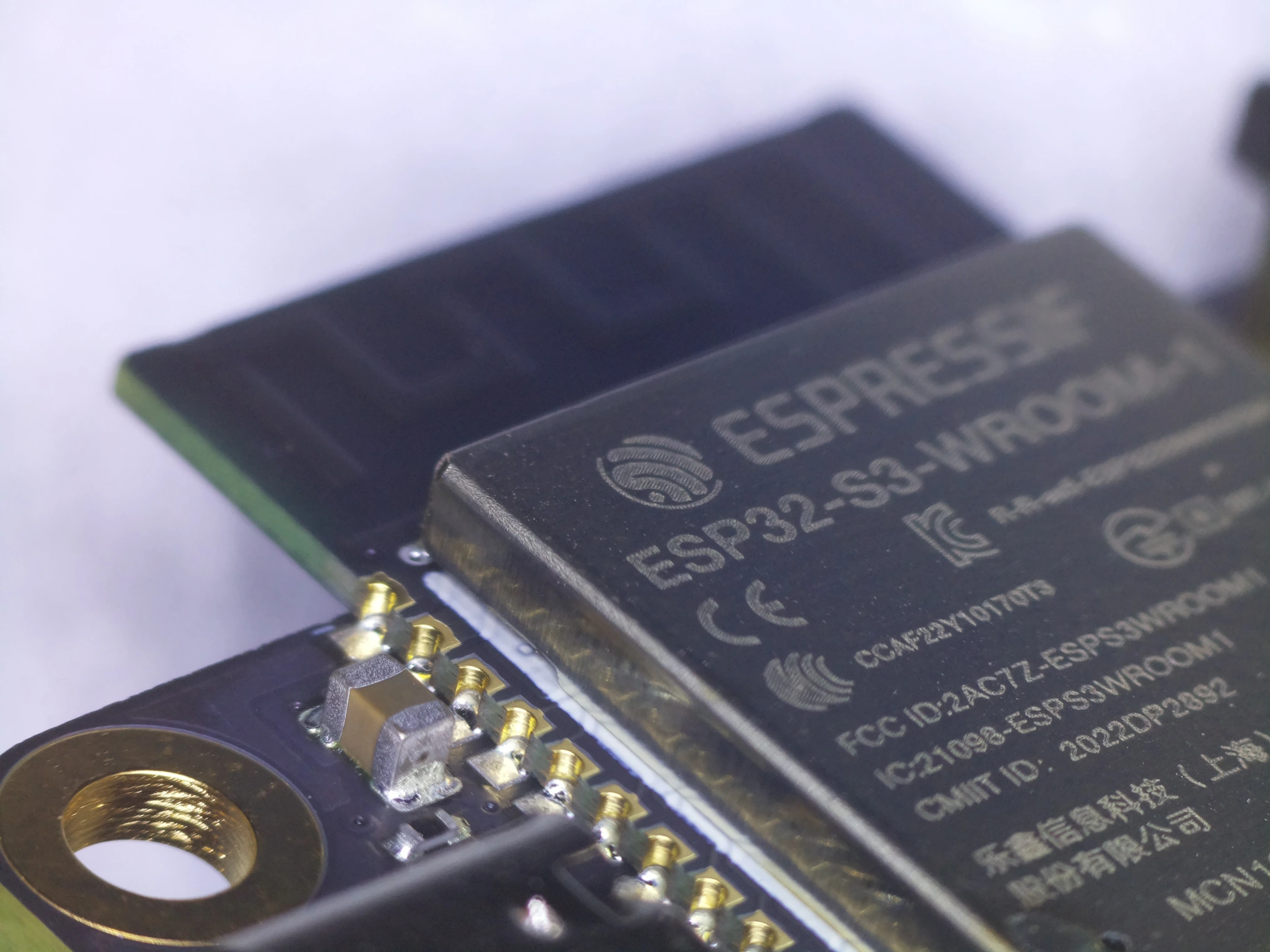
ESP32-S3, on the Falcon Core board
The ESP32-S3-WROOM-1 was the obvious choice. It has a native DVP camera interface that directly supports the OV2640, dual-core 240MHz LX7 processors, Wi-Fi and BLE, native USB, and up to 8MB of PSRAM for frame buffering. The N8R8 variant (8MB flash, 8MB PSRAM) gave me enough room for double-buffered camera frames at reasonable resolutions, without starving the firmware of RAM.
The module comes in a castellated package that solders directly to the PCB, which saves a ton of space and weight, since I don't need to account for headers and sockets like I did with the Falcon Flight board. One of the greatest advantages of using the ESP32-S3 is that it's also well-documented, with Espressif's ESP-IDF providing mature drivers for every peripheral I need: the camera DVP interface, I2C, LEDC (for motor PWM and camera XCLK generation), and the ADC.
One thing I learned quickly during pin planning is that the ESP32-S3 has a lot of GPIO, but not as many as you think once you start allocating them. The camera alone consumes 14 pins (8 data lines, PCLK, XCLK, VSYNC, HREF, and 2 for SCCB). Four bidirectional motor drivers need 8 pins, using the DRV8212P motor driver. I2C for the sensor suite takes 2 more. USB takes 2. Battery ADC and status LED take a few more. That's 28 pins planned out, not even considering conflicts with the internal flash and PSRAM bus, which silently consume GPIO26-37 on the N8R8 variant, or the BOOT/EN pins. Planning the final pinout was one of the more tedious parts of the design, but getting it right meant no bodge wires and no pin conflicts at bringup.
The Board
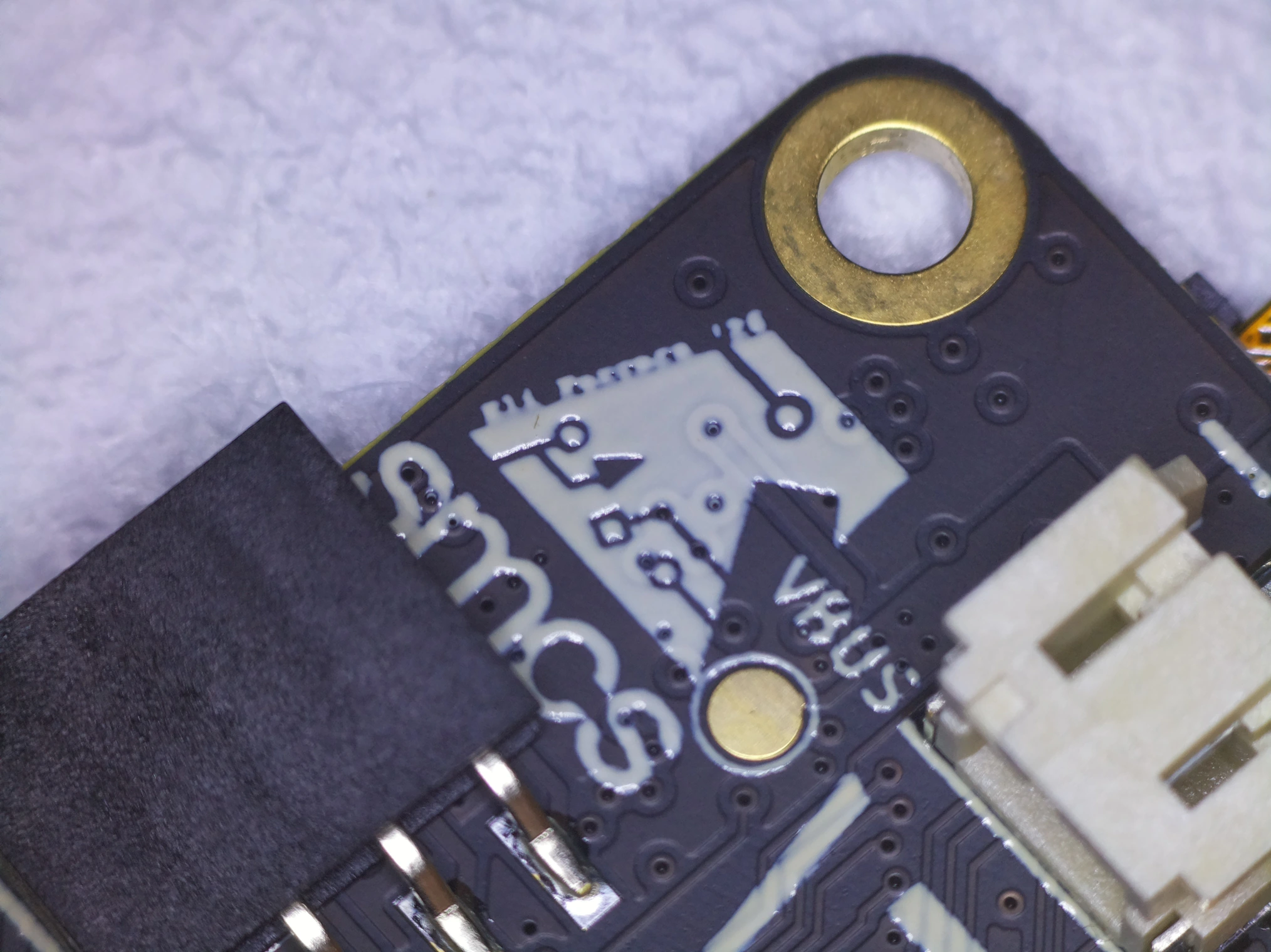
SMCS Logo next to gold-plated mounting holes, contrasted against a matte black soldermask
The Falcon Core board is a 32×46mm 4-layer board designed in KiCad, and manufactured by PCBWay. The stackup uses standard FR-4, but I elected for matte black solder mask from PCBWay for the aesthetics, and to differentiate this board from the Falcon Flight board.
Four layers were necessary for two reasons. First, the component density on this board was probably the highest of any board I've made yet, and even 4 layers was cutting it close in some regards, especially around the motor drivers. Second, it allowed for dedicated ground and power planes that provide low-impedance return paths for the ESP32-S3's high-speed signals, which improves their signal integrity.
The MMC5633NJL's tiny WLP package (0.85×0.85mm, 4 balls) was so small that it was actually a manufacturability concern. Despite it falling within PCBWay's standard BGA/WLP capabilities, it wasn't manufacturable using traditional HASL finish; the engineers at PCBWay insisted that I use ENIG plating. This frankly improved the look of the board; real gold + matte black is a stunning aesthetic.
Sensors
BMI270 — 6-Axis IMU
The BMI270 is a 6-axis accelerometer and gyroscope from Bosch Sensortec, and it's the same IMU I used on the final revision of Falcon Flight, where it worked flawlessly on the first try. It's a 16-bit tri-axial accelerometer and gyroscope, that relies on MEMS technology. Inside the package (only 2.5×3.0mm) tiny capacitive structures connected to a known mass swing back and forth as forces act on it. Since the capacitance changes proportionally to how far the known mass swings, acceleration can be calculated from that. In addition, angular velocity is measured using more advanced sensing leveraging the Coriolis force (Coriolis vibratory principles.)
This sensor provides acceleration and angular velocity data over I2C, which feeds directly to the dashboard, with the fusion.h header providing an easy entry point for a Madgwick or Mahony sensor fusion filter running on the ESP32-S3 to be added later. Currently, estimates of the blimp's attitude (roll, pitch, yaw) are just run through a complementary filter, with a high-pass on the gyro to kill drift over time, and low-pass on the accelerometer to reject short-term linear acceleration noise. On the blimp, the IMU's primary jobs are attitude estimation for tilt compensation of the magnetometer, heading hold during station-keeping, and detecting bumps or disturbances. Dead-reckoning position from accelerometer integration was something I wanted to try, but it simply wasn't viable at these speeds and timescales; the drift was enormous, so position sensing hasn't been implemented yet.
MMC5633NJL — 3-Axis Magnetometer
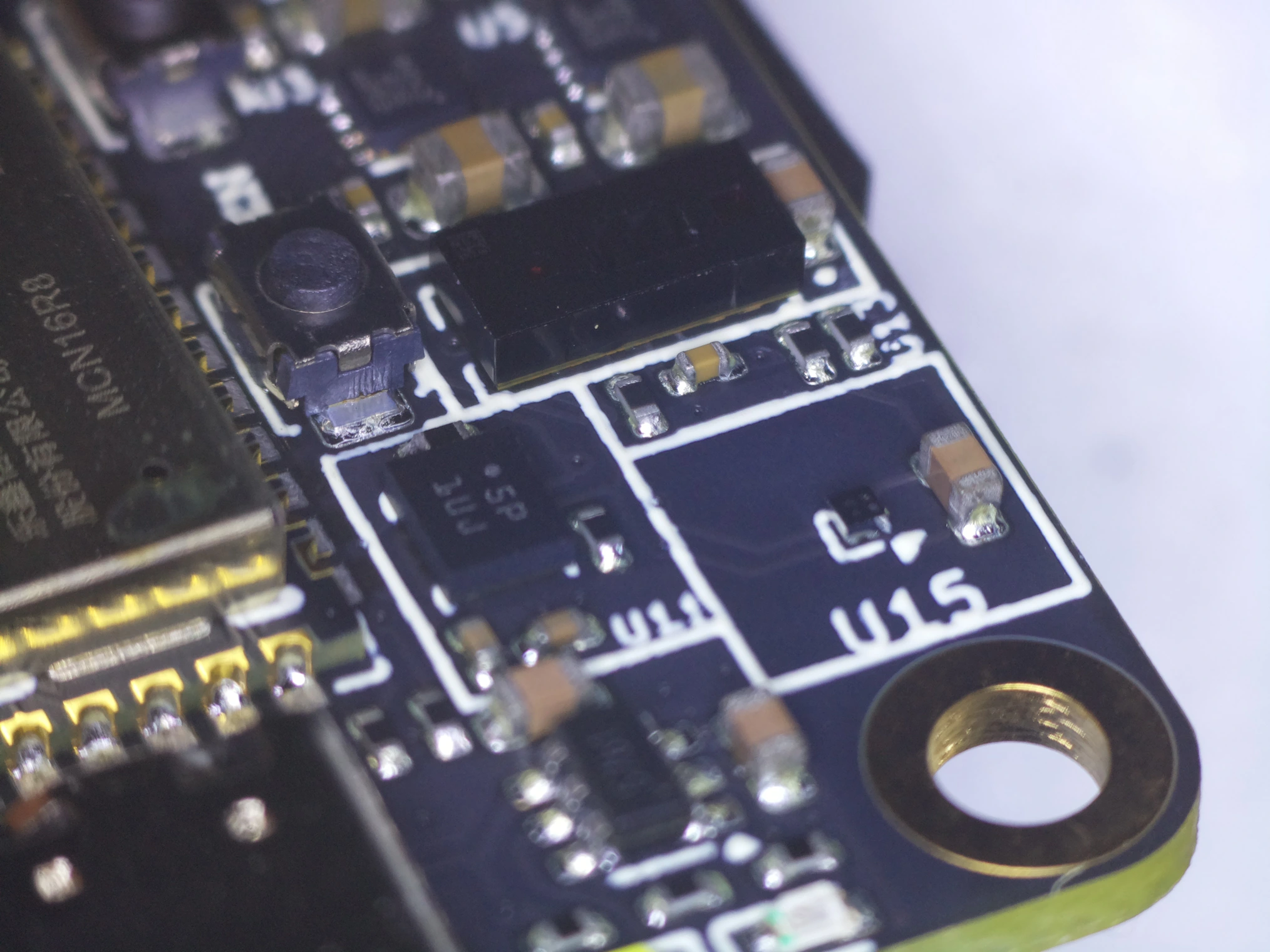
Accelerometer, gyroscope, magnetometer, and ToF sensor
The magnetometer was one of the more painful components on this project. I originally designed around the Bosch BMM350, which required a dedicated 1.8V power rail (adding a fourth LDO to the board) and came in a tiny 1.28×1.28mm WLCSP package. After running into stock issues, I switched to the MEMSIC MMC5633NJL, an AMR (anisotropic magnetoresistive) magnetometer with 20-bit resolution and built-in SET/RESET degaussing. There were a few advantages to this component swap:
- It runs on 1.62-3.6V, so it connected directly to the 3.3V rail. This eliminated an entire LDO + passives from the board, meaning one fewer potential failure point, and a small weight savings.
- It was over 3× cheaper than the BMM350 on LCSC, which meant a genuine cost savings, while still maintaining all of the functional requirements I wanted it to fulfill.
- It was actually in stock. At the time of writing this blog post, the BMM350 has reasonable stock, but when I was sending off for manufacturing, the BMM350 was totally out of stock, with a lead time of a few weeks-- not ideal for quick prototyping.
The MMC5633NJL came in a 4-ball 0.85×0.85mm WLP; genuinely tiny, and definitely the smallest IC I've ever used, but PCBWay's assembly line handles it without issue.
Magnetic isolation for the magnetometer was a significant layout concern. Between the motors themselves acting as large, unshielded inductors, and the motor drivers pushing current through traces that also generate magnetic fields, the environment was already noisy enough. On top of that, the board is only 32×46mm, and there isn't much room to separate the magnetometer from those current paths. Thankfully, the magnetometer's position doesn't matter at all in terms of proximity to the center of rotation; it doesn't sense translation at all, and worst-case, translating by a few centimeters during a full rotation won't meaningfully upset the sensor's readings in any reasonable flying environment.
The layout strategy was to place the MMC5633NJL at the board edge, cut the ground plane on all layers beneath the sensor, and route motor current paths as far away as possible. Critically, the ground plane cutout prevents any conductive loops near the sensor that could inadvertently create eddy currents that would distort the sensitive measurements. I initially considered adding exposed copper or a solder bead around the sensor as a shield, but that would actually make things worse; magnetic shielding at DC frequencies requires high-permeability materials, not copper, and such materials would block the Earth's field that the sensor is trying to measure anyways. I managed a copper keepout zone of 6.5×6.25mm; twice the recommended keepout from the manufacturer footprint.
I chose to be so liberal with this keepout zone because I had problems in the past with the magnetometer: on the Falcon Flight board, despite my best efforts, I could never get consistent compass functionality. It was likely a mix of poor calibration, having multiple ground planes under the magnetometer, and having noise from the Raspberry Pi Zero 2W couple into the sensor, but they all contributed to a nearly useless sensing experience. I initially also considered adding exposed copper or a solder bead around the sensor as a shield before I really knew what I was doing, but apparently that actually makes things worse: magnetic shielding at DC frequencies requires high-permeability materials (like mu-metal), not copper, and such materials would block the Earth's field that the sensor is trying to measure. Even with careful layout, the raw magnetometer data requires full ellipsoid calibration, including a hard-iron offset vector plus a soft-iron correction matrix to produce usable compass headings. Once calibration is complete, however, it is saved to the board, and direction tracking works nearly as well as the compass on my phone!
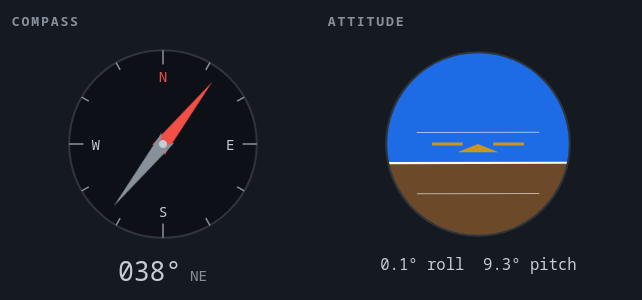
Web dashboard showing calibrated compass + navball operating on live telemetry data
VL53L5CX — Time-of-Flight Sensor
The VL53L5CX is an 8×8 multizone ranging sensor from STMicroelectronics, communicating over I2C. This is the one new sensor on the board, and (in my opinion) very cool technology. This Time-of-Flight (ToF) sensor works by emitting infrared (940nm) light, and timing how long it takes for that light to bounce off of a surface and hit the sensor's Single Photon Avalanche Diode (SPAD) array. This is an array of pixels that can detect a single photon of 940nm light hitting the sensor, allowing for extremely precise and consistent detection of the emitted IR light. From that, calculations can be made to reveal the distance the light traveled, hence the distance from the object it bounced off of. This results in an 8×8 array of distance values, i.e. a 64-pixel low resolution depth camera; no transformer model or inference needed. On the blimp, it's mounted facing downward for altitude measurement, providing an absolute height reference that the PID loop uses for station-keeping. Unlike a barometer, which would be useless indoors at these altitudes, the ToF sensor gives direct distance measurements to the floor with millimeter-level resolution. The multizone capability also opens up the possibility of crude terrain mapping or obstacle detection in the downward field of view, though for now it's used purely for altitude.
Motor Drivers
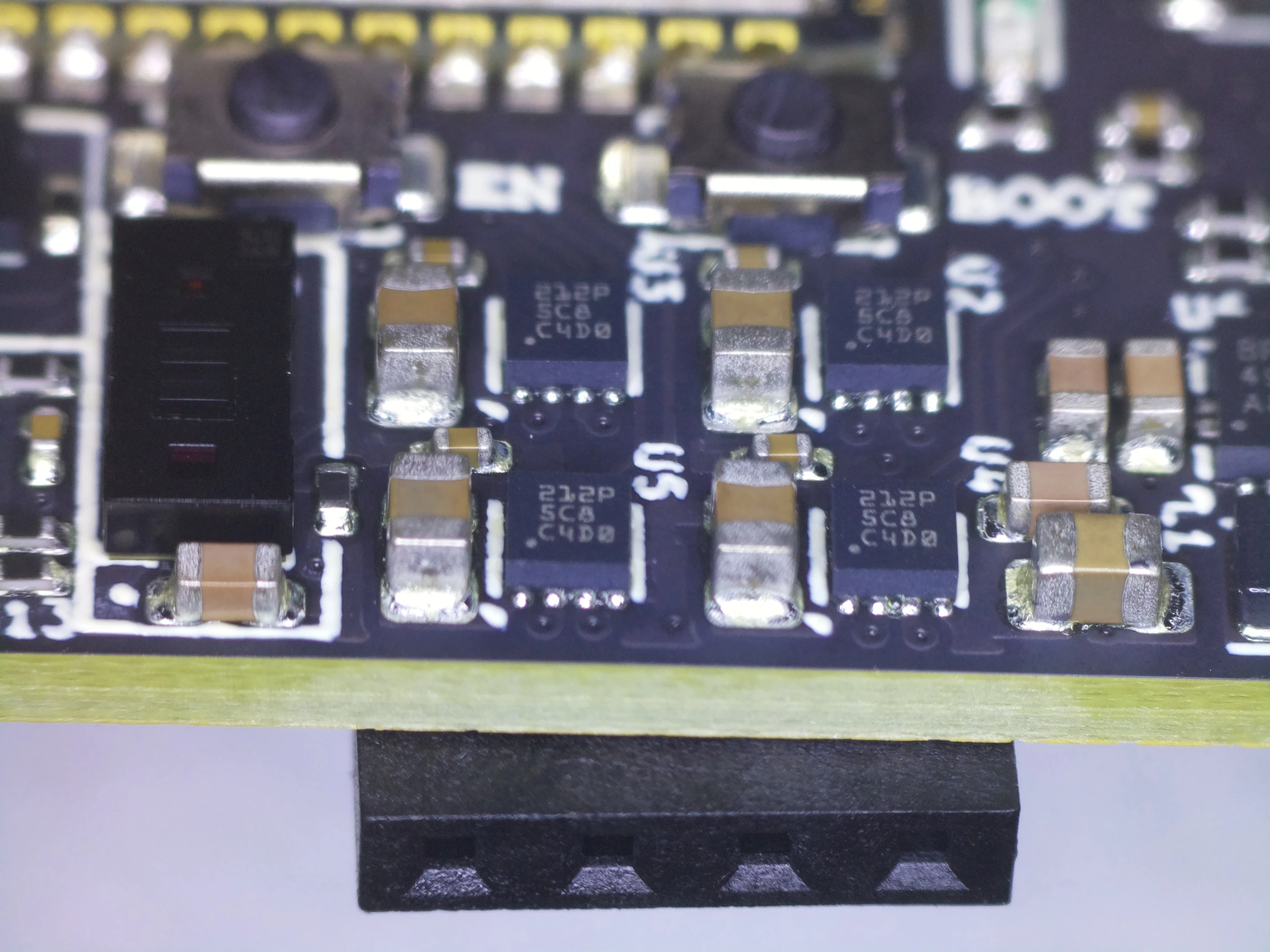
4x DRV8212P motor drivers, routed to 2x 4-pin 2.54mm connectors
I used four DRV8212P motor driver ICs from Texas Instruments, each driving a single brushed DC motor bidirectionally. This is the same IC I settled on for the final revision of Falcon Flight, and it was one of the best component choices I made on either project. The DRV8212P is a dual half-bridge driver in a 2×2mm WSON package, and it solved several problems simultaneously.
The most important feature is the built-in dead-time generation for sudden motor reversals. On Falcon Flight, I learned the hard way that the DRV8833's internal clamping diodes couldn't handle aggressive direction changes; after slamming the motors from forward to reverse a few times, the drivers would fail. Since I'm designing this board for students who will absolutely slam the motors in every direction, I needed a driver that could handle abuse without external protection circuitry. The DRV8212P provides this, both by providing dead time generation and integrated protection and current regulation. While the DRV8212P's internal controller staging dead-time automatically feels oddly specifically tailored to my use case, since any professional would know about motor flyback when designing a PCB with integrated motor drivers, I appreciate it nonetheless; thanks TI.
At 2×2mm each, four DRV8212Ps take up roughly the same board area as a single DRV8833 in its 4×4mm WQFN package, but with the added benefit that a single driver failure only takes out one motor instead of two. They also have a lower minimum supply voltage (1.65V versus the DRV8833's 2.7V), which gives more headroom as the LiPo sags under load; the 3.3V power regulator would die before the motor drivers stop functioning, although the battery really shouldn't be allowed to discharge so deeply that it gets to that point.
The EN pin on the DRV8212P has an internal pull-down, which means I don't need external pull-down resistors on the IN1/IN2 lines as long as the firmware drives those pins low before asserting enable. That saved me significant board space and a real layout headache. With that extra board space, I was able to cram much more bulk capacitance on the VM pin of the DRV8212P; I managed to place a 47uF, 6.3v MLCC capacitor right next to the VM and GND pins, all in only a 0805 package.
Motor power is fed directly from the battery to the DRV8212P VM pins, bypassing the logic LDOs entirely. A ferrite bead isolates the logic rail from the motor power path, attenuating high-frequency switching noise from the motor drivers before it reaches the ESP32-S3 and sensors. This doesn't prevent battery voltage sag during motor spool-up, but it keeps the fast voltage dips from corrupting sensor readings or crashing the processor. Two of the motors face forward for horizontal thrust, and two face downward for altitude control.
Camera
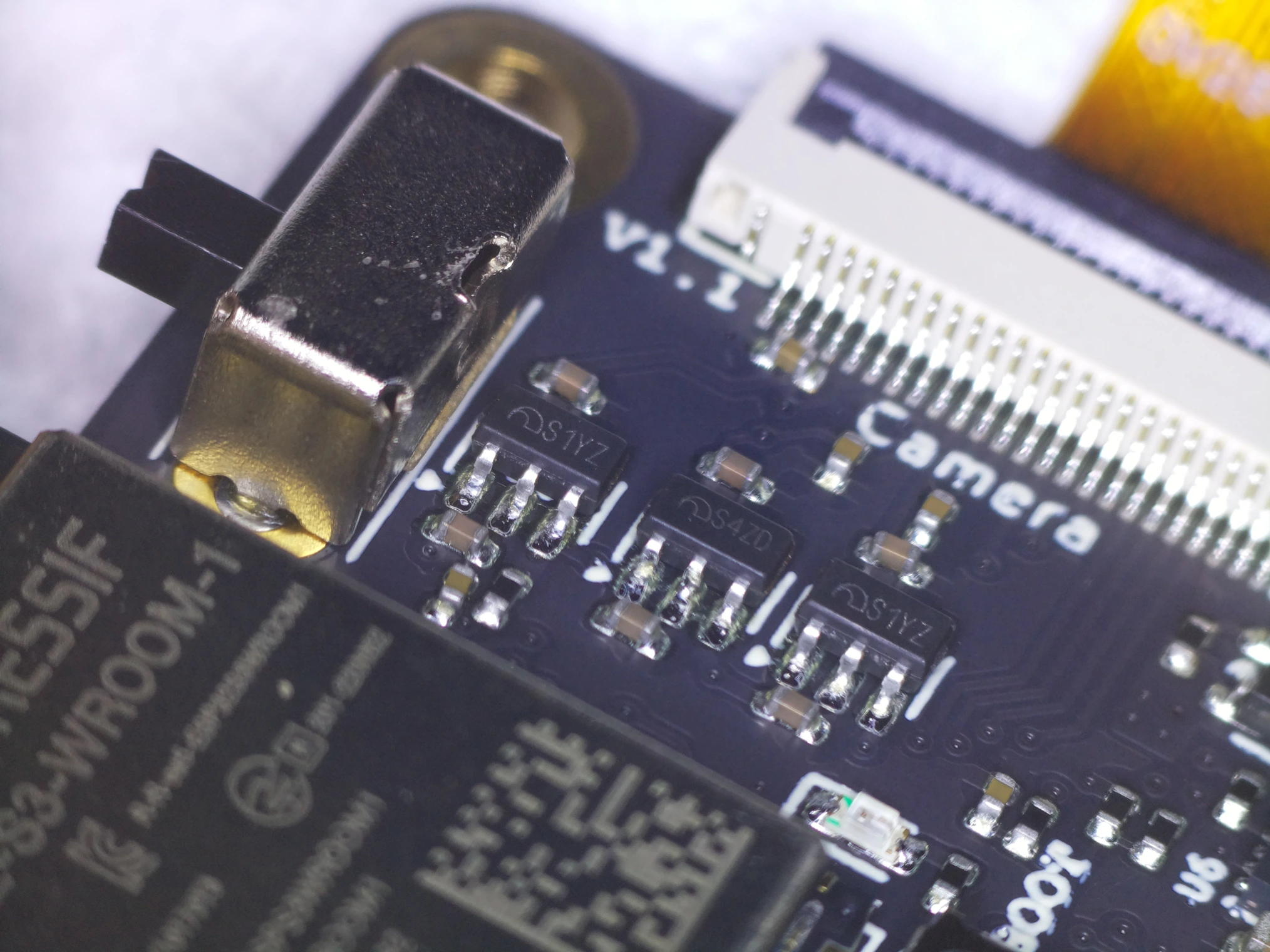
3x SOT-23-5 LDOs behind the camera connector
The OV2640 connects via a 24-pin 0.5mm FFC flip-latch connector, interfacing with the ESP32-S3 through an 8-bit DVP bus. I'm using a cheap, basic 60° field-of-view module, but have plans to scale up to a 120° FOV module, which would be wide enough for optical flow to work at the blimp's slow airspeeds without requiring excessive resolution.
Power for the camera module comes from dedicated LDOs rather than on-module regulators: two ME6211C28s provide separate 2.8V rails for AVDD (analog) and DOVDD (digital I/O), and an ME6211C12 provides 1.2V for DVDD (digital core). Keeping AVDD and DOVDD on separate regulators prevents digital switching noise from coupling into the analog sensor domain, which would degrade image quality according to the OV2640 datasheet. I heavily referenced the AI Thinker ESP32-CAM reference schematic for this sensor integration.
The camera LDO enable pins are all tied to 3.3V (always on) rather than controlled via GPIO. This was a deliberate choice, as GPIO-controlled power switching consumed additional pins that I simply didn't have available; every single one was used up by the end of the design. Software standby via the SCCB (I2C-like) interface achieves the same power savings when the camera isn't needed, without the hardware overhead.
I made the camera configuration run on its own I2C bus (GPIO1/2 for SCCB SIOD/SIOC), separate from the main sensor bus. The ESP32-S3 has two I2C peripherals, so splitting them costs nothing in hardware and avoids timing weirdness from the SCCB protocol during camera initialization. It's just typical to keep the camera's SCCB on its own bus.
Power Architecture
One of the biggest wins of moving from a Pi-based design to the ESP32-S3 was eliminating the boost converter entirely. The Raspberry Pi needs 5V, which meant boosting the 3.7V LiPo, and that boost converter (an MT3608) was a constant source of problems. Junction capacitance in the output diode alone was enough to cause instability, and using a cheap, non-name brand regulator meant serious reliability problems. In early prototypes of the Falcon Flight board, I actually only used a single battery, but I naively used a converter with no real specification for input voltage fluctuation performance, so when more than a single motor turned on at once, the voltage sag caused a complete board reset; not ideal, and it eliminated a large portion of the weight savings I had originally anticipated. With the ESP32-S3, everything runs at or below battery voltage, so the entire logic system is powered by a single 3.3V high-efficiency converter: the TPS63001.
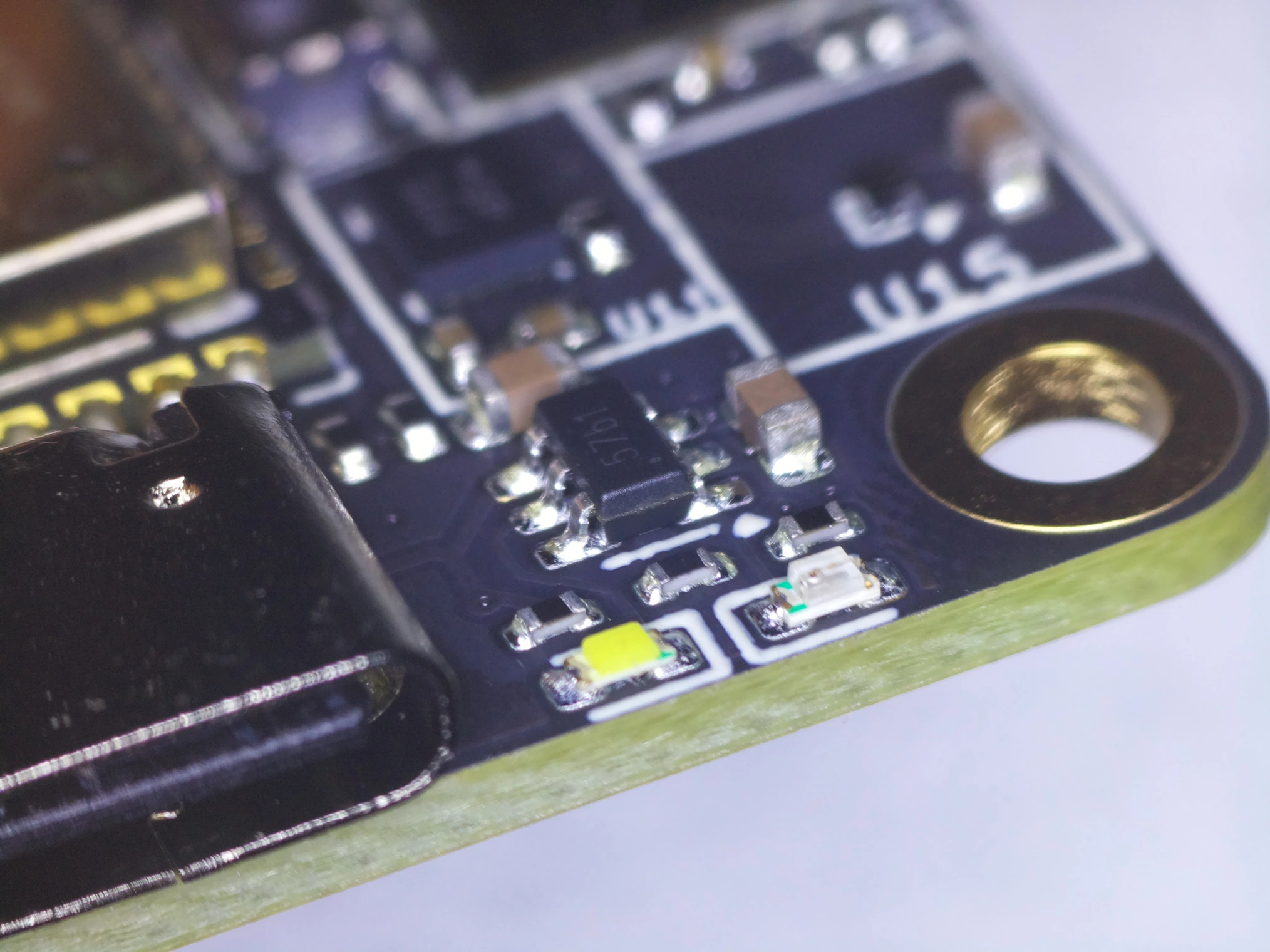
TP4057 battery charger IC, next to USB-C port
The battery is a BetaFPV 300mAh 1S LiPo, charged via USB-C through a TP4057 linear charger. The USB-C connector has 5.1kΩ pull-downs on CC1 and CC2, which tells the upstream USB-C source to provide 5V. The TP4057 is a much more compact charger than the TP4056, which is a much more popular but frankly outdated IC. Meanwhile the TP4057 comes in an SOT23-6 instead of SOIC-8, and it doesn't require the external DW01a and FS8205a battery protection ICs.
Before the battery voltage reaches the power regulators or the motor drivers, it runs into a P-channel MOSFET first, for power control. With the gate pulled up by a 100kΩ resistor, it blocks the battery voltage from entering by default. When the physical power switch on the side of the board is flipped, connecting the gate to GND, the MOSFET allows current to pass into the rest of the power tree downstream. This design choice puts much less strain on the contacts of the switch, which now only need to handle microamps of current, rather than the entire power budget of the board, which reduces pitting on the contacts, not to mention that it would certainly be more than the modest 500mA current rating on the physical switch itself.
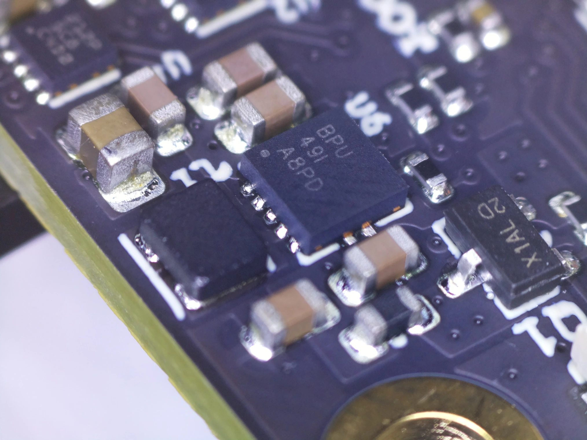
TPS63001 3.3V switching regulator + power switch
The power tree splits immediately after the battery: Motor power goes directly to the DRV8212P VM pins, as the motors run on raw battery voltage (3.0-4.2V), which is well within the DRV8212P's 1.65-11V range. Logic power passes through the ferrite bead, then fans out to the TPS63001, and three ME6211-family LDOs: two 2.8V rails for the camera's analog and digital I/O supplies; and a 1.2V rail for the camera's digital core. All three LDOs share the same SOT-23-5 footprint and pinout, which simplified layout and BOM management considerably.
Battery voltage sensing uses the ESP32-S3's internal ADC1 on GPIO7 at 12 dB attenuation, fed through a 2:1 resistive divider that halves the 1S LiPo's voltage into the ADC's usable range. Each reading supersamples the ADC 64 times and averages the results to suppress noise, and the ESP-IDF curve-fitting calibration API converts the raw counts to millivolts using the chip's factory calibration data to correct the ADC's offset and nonlinearity. State of charge is then estimated with a simple linear map from 3.0 V (empty) to 4.2 V (full).
Software Architecture
The firmware runs on ESP-IDF, using FreeRTOS across both cores. The control loop is pinned to one core, handling the real-time control loop, performing sensor polling, sensor fusion, PID computation, and motor PWM output. Meanwhile, the camera DVP and networking are allowed to execute unpinned across both cores, since they are by far the most computationally intense software blocks.
Telemetry communication with the laptop is over WebSocket, while the board streams MJPEG frames to the laptop. Position and heading corrections are sent back over the WebSocket connection, where the ESP32-S3's PID controller uses them alongside the onboard IMU and magnetometer data to hold position.
This is explicitly not an ArduPilot system. ArduPilot is designed for fast, aerodynamic vehicles with conventional flight dynamics. A blimp is slow, buoyant, has a huge drag coefficient, and its control profile is fundamentally different. A custom PID-based stabilization loop tuned for the blimp's specific dynamics is ideal. Though I made a solid attempt at this PID loop, I was only able to get it to stay in one place within ±0.5 meters, with constant overcorrection; with the PID station-holding loop enabled, the battery drained in a matter of minutes with the motors constantly spinning.
Conclusion
Three full discharge runs on the 300mAh 1S LiPo, logged from the onboard ADC. All three hold above 3.0V for most of the run before falling off the cliff.
The Falcon Core board works exactly as intended; I have no complaints. I was able to cram more sensors into a smaller footprint, fix design errata from the Falcon Flight board, and even add an entire integrated camera, all while increasing idle battery life by about 50%, and reducing weight by nearly 2.5x! The camera is responsive, the wifi works very reliably thanks to the ESP32-S3 module placement, and all of the sensors work together in harmony to create a very responsive and impressive telemetry experience.
What I Would Improve
Although every sensor and system works without any real issue, there are always a few ideas in my projects that never make it to production:
- Get rid of the ESP32 module, and use the bare ICs themselves. I could reduce weight by a few grams by omitting the extra PCB and copper, but the largest downside would be that I would need to recreate the PCB antenna, and that would certainly require atleast one extra spin to tune the antenna with a VNA. I could also lay out the ICs in a way that makes the most sense for my board, and the vertical height would be uniform throughout the top side.
- Even more sensors. Although the sensing suite on this board is more than enough, I had considered the idea of adding more than one camera, or even a higher resolution ToF sensor. I really would have liked to get enough resolution to get an actual depth map, and 8×8 just isn't quite enough. Between a higher resolution ToF and an additional downwards-facing camera, I may have been able to create real depth maps in realtime, but the practicality of multiple cameras on an already GPIO-constrained platform meant that it never left the drawing board.
- Real position tracking. The ESP32 is simply too compute constrained to do the computation required for realtime optical flow at a reasonable resolution, let alone a facial recognition model. Since the hardware is complete, I would like to implement local optical flow that can update the blimp via websocket in the future, but since PID station keeping was barely a success, it seemed like a difficult task given the fundamental constraints of any hardware on this slow-moving blimp platform.
This board was sponsored by PCBWay, but it isn't meant to just live in a box in my closet after this is posted. These boards will become the future of the SMCS Blimp project, and allow students to take remote flight further than ever before.
Thanks for reading! Hardware schematics and KiCad files are available on the project's GitHub page. The original Falcon Flight project lives here.